Device with direct control, in particular proportional and/or rectilinear control, for fluid loading and/or unloading system

A loading system and control device technology, applied in control/regulation systems, general control systems, liquid distribution, transportation or transfer devices, etc., can solve the problem of increasing obstacles or the danger of target pipelines, making it difficult for operators to connect pipes, and damage pipes Joint sealing and other issues

Active Publication Date: 2011-01-05
FMC TECH INC
View PDF0 Cites 10 Cited by
  • Summary
  • Abstract
  • Description
  • Claims
  • Application Information

AI Technical Summary

Problems solved by technology

More generally, it is difficult for the operator to accurately control the motion of the coupling, which increases the risk of the coupling striking an obstacle or the target pipeline
This may damage the seal of the fitting

Method used


Image

  • Device with direct control, in particular proportional and/or rectilinear control, for fluid loading and/or unloading system
  • Device with direct control, in particular proportional and/or rectilinear control, for fluid loading and/or unloading system
  • Device with direct control, in particular proportional and/or rectilinear control, for fluid loading and/or unloading system

Examples


Embodiment Construction

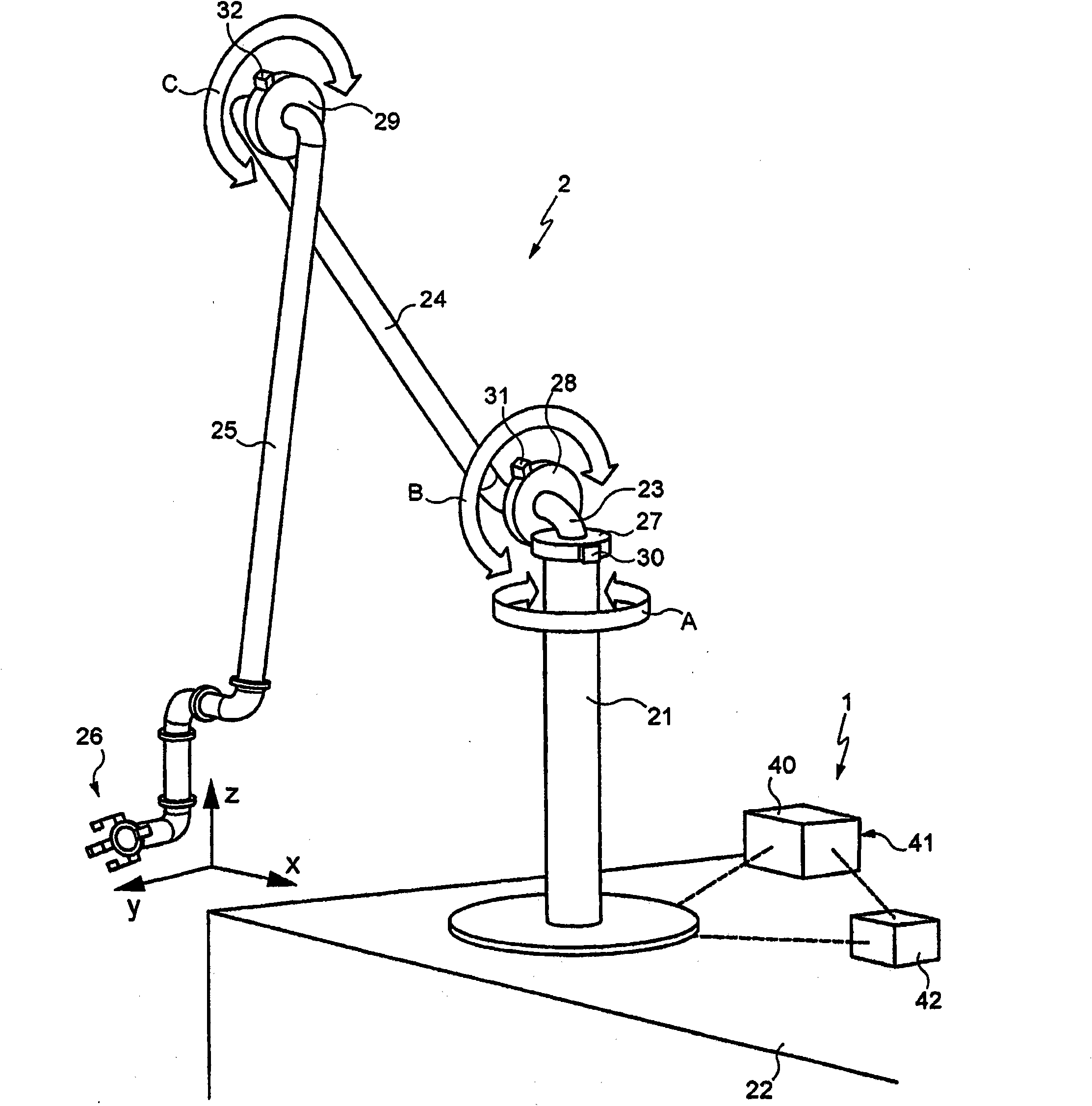
[0037] figure 1 A loading arm 2 equipped with a control device 1 according to the invention is shown very schematically. Here the loading arm is shown very simplified and it should be pointed out that the control device according to the invention can be used in any type of marine loading system, in particular the system described above.

[0038] figure 1 The loading arm has a base 21 connected to a fluid tank located below a surface 22 on which the base is fixed and which may be, for example, a dock or the deck of a ship. An elbow 23 is pivotally hinged at the top end of the base to which is hinged a first tube, also called inner tube 24 , whose opposite end is hinged to a second tube, called outer tube 25 . The outer tube ends with a nipple 26 suitable for connection to a target pipeline (not shown), for example on a ship. In a known manner, the pipe connection has three rotational degrees of freedom relative to the end of the outer pipe. These three rotations are free, s...


PUM


Abstract

The invention concerns a control device for the movement and positioning of a coupling for a marine loading system (2), said marine loading system comprising at least one fluid transfer line having a line end fixed to a base, and a moveable line end provided with a coupling adapted for connection to a target duct, the system further having a plurality of mechanical connections such that the coupling has at least three degrees of freedom relative to the base, the device comprising at least three proportional control actuators (27, 28, 29) each for proportionally controlling the movement of thesystem in a degree of freedom, a position sensor (30, 31, 32) of the system tracking each degree of freedom, an operator input interface (60) for inputting commands to move the coupling, and a calculator (41) for calculating the instantaneous position of the coupling from the information provided by the sensors, and for calculating, from movement command inputs of the input interface, simultaneous control instructions to give to each of the actuators such that their combined movements result in a movement of the coupling corresponding to the movement command provided by the operator at the input interface.

Description

technical field [0001] The present invention relates to a fluid loading and / or unloading system for a ship, commonly referred to as a marine loading system. These systems are used to transfer liquid or gaseous products between a ship and a terminal or between two ships. [0002] More particularly, the invention relates to devices for controlling the movement and positioning of such loading and / or unloading systems. Background technique [0003] Typically, an offshore loading system has a fluid transfer line end secured to a base and connected to a tank for the fluid to be transferred, and an opposite line end that is movable and has a coupling for connection to a target pipeline, the target pipeline Connects itself to a fluid tank. [0004] Two types of marine fluid loading systems are known, which differ in their construction: those transported by rigid pipes and those transported by hoses. [0005] In systems with rigid tube transfers, the loading arm system and the tel...

Claims


Application Information

Patent Timeline
Patent Type & Authority Applications(China)
IPC IPC(8): B67D5/68B67D9/00B67D9/02
CPCB67D9/00B67D9/02B63B27/24G05B2219/45045B25J9/1689Y10T137/0318Y10T137/8275Y10T137/8807
Inventor N·西拉尔德
Owner FMC TECH INC
Why Eureka
Try Eureka