Automatic sludge discharging system for mine sump

A technology of automatic drainage and water tank, applied in chemical instruments and methods, separation methods, sedimentation separation, etc., can solve the problems of harsh working environment, incomplete solid-liquid separation, low cleaning efficiency, etc., and achieve simplified mine water treatment system , The roadway excavation technology is mature, and the effect of saving infrastructure time

Inactive Publication Date: 2011-12-07
HENAN POLYTECHNIC UNIV
View PDF6 Cites 0 Cited by
  • Summary
  • Abstract
  • Description
  • Claims
  • Application Information

AI Technical Summary

Problems solved by technology

This traditional method not only has a large workload, but also takes a long time to clear and excavate, and the working environment is harsh, and it is difficult to clean and excavate
[0004] Mechanized cleaning of mine water bins has been a difficult problem that coal mining enterprises have been eager to solve for many years. However, over the past few decades, dozens of cleaning machines have been developed in my country but have not been popularized and used. The main reason is that the situation in the mine is complex and changeable. The water tank dredging equipment and its supporting systems have disadvantages such as single performance, low dredging efficiency, and incomplete solid-liquid separation, which cannot adapt to the complex and changeable working environment of underground water tanks; most designs still need to release water before clearing the tank to achieve mechanization At the same time, it failed to avoid the disadvantage of manual liquidation

Method used


Image

  • Automatic sludge discharging system for mine sump
  • Automatic sludge discharging system for mine sump
  • Automatic sludge discharging system for mine sump

Examples


Embodiment 1

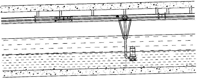
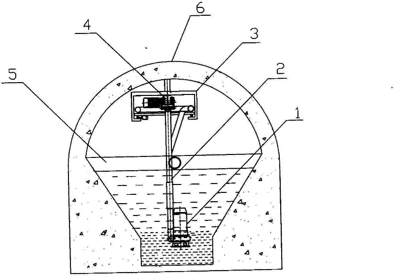
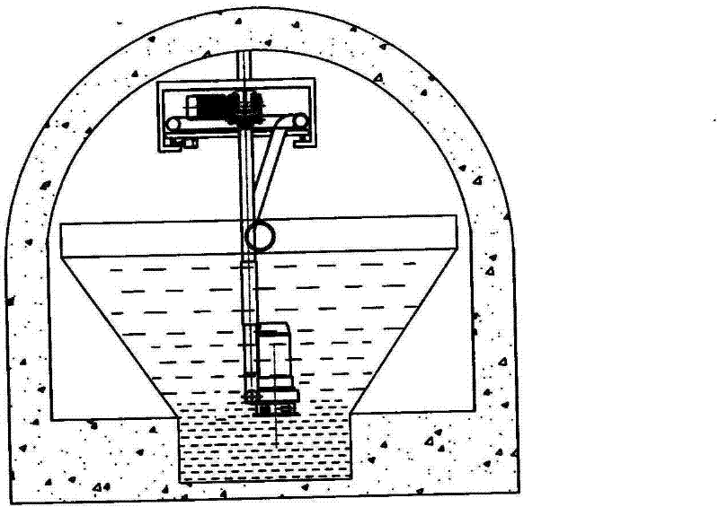
[0036] Such as figure 1 , figure 2 , Figure 4 As shown, the system of the present invention includes the concentrated sedimentation tank 5 arranged in the underground roadway, the guide rail device whose length at the top of the concentrated sedimentation tank in the erected roadway is greater than the length of the concentrated sedimentation tank, installed on the guide rail device fixed frame 3 both sides in parallel The mobile coil mechanism 10 on the mobile coil mechanism slideway 11 (see Figure 5 ), the monorail trolley 8 formed by the guide wheel and the driving mechanism is installed in a suspended manner on the monorail 7 arranged along the longitudinal central axis of the guide rail device fixture 3, and the monorail crane 4 is hoisted on the monorail through the connecting rod 2 The slurry pump 1 at the bottom of the crane 4; the moving coil mechanism (see Figure 6 ) includes a vehicle 16, a turntable 12, and a slag discharge pipe 9 coiled on the turntable. Th...

Embodiment 2

[0040] Such as Figure 9 , Figure 10 , Figure 11 As shown, the slag discharge pipeline section located between the turntable and the slurry pump in the present invention can also be suspended under the single guide rail through a plurality of pulley hoisting frames 19 . Specifically: arrange some pulley hoisting frames 19 on the single guide rail 7, and select a node to be fixed on the pulley hoisting frame 19 every other suitable length on the slag discharge pipeline; the length of the single guide rail 7 will be slightly longer than the length of the sedimentation tank, So that when the slag discharge pipeline is fully compressed, the slurry pump can be located at the endpoint of one end of the sedimentation tank, and when the slag discharge pipeline is fully extended, the slurry pump can reach the endpoint of the other end; when the monorail crane drives the slurry When the pump moves away from the outlet end, due to the effect of traction, the pulley hoisting frame 19 ...

Embodiment 3

[0042] The device of the present invention can also be used as Figure 12-13 In the embodiment shown, specifically, a moving coil mechanism is used to suspend the slurry pump on the top of the thickening roadway. The moving coil mechanism is connected with a transmission device and can reciprocate along a track erected on the top of the roadway. Back and forth between the two ends of the concentrated sedimentation tank. The inlet pipe of the slurry pump is connected to the concentrated underflow, and the slurry is pumped while moving with the moving coil mechanism. The slag discharge pipe of the slurry pump is wound on the moving coil mechanism, and can expand or contract with the movement of the moving coil mechanism: when the moving coil mechanism moves towards one end of the thickening roadway, the slag discharge pipe is gradually moved Rolled into the moving coil mechanism until it moves to the end point; when the moving coil mechanism moves towards the other end of the t...


PUM


Abstract

The invention relates to an automatic sludge discharging system for a mine sump. The system comprises a concentration and sedimentation basin, a guide rail device, a moving coil mechanism, a monorail crane and a slurry pump, wherein the concentration and sedimentation basin is arranged in underworkings; the guide rail device is arranged at the top of the concentration and sedimentation basin in the underworkings; the moving coil mechanism is arranged on moving coil mechanism slide rails arranged on both sides of a guide rail device fixing bracket in parallel; the monorail crane is installed on a monorail arranged along the longitudinal central axis of the guide rail device fixing bracket through a guide wheel and a driving mechanism in a suspension mode; and the slurry pump is suspended to the lower part of the monorail crane. The moving coil mechanism comprises a carrier vehicle, a rotary disc and a slag discharging pipe wound around the rotary disc, wherein the carrier vehicle is placed on the moving coil mechanism slide rails through roller wheels arranged on both sides of the bottom surface and driven by a power source, and a vertical shaft for installing the rotary disc is arranged in the central part of the plane of the carrier vehicle; the rotary disc is combined with the vertical shaft arranged in the central part of the plane of the carrier vehicle through an axle hole arranged in the central part in a movable fit mode.

Description

technical field [0001] The invention relates to an automatic desilting system for a mine water tank, which is used for processing underground mine water, and can separate the mine water from impurities therein for separate treatment, thereby solving the difficult problem of desilting the underground water tank. Background technique [0002] Coal mine water refers to all the water that seeps into the underground mining space during the coal mining process. Mine mines are generally equipped with special water tanks. Mine water is collected in the mine water tank and then pumped out of the well by the drainage system. The mine water tank is an important facility for safe production in coal mines and prevention of mine floods. Since the mine water contains a large amount of impurities mainly including coal slime and sand, these solid particles will be carried into the water tank by the mine water and will be deposited at the bottom of the water tank, resulting in a decrease in t...

Claims


Application Information

Patent Timeline
Patent Type & Authority Patents(China)
IPC IPC(8): B01D21/00
Inventor 焦红光刘松王海娟孙伟赵继芬
Owner HENAN POLYTECHNIC UNIV
Why Eureka
Try Eureka