
Parallel counter-rotating triple-screw extruder

A technology of three-screw and extruder, applied in the direction of mechanical equipment, gear transmission, belt/chain/gear, etc., can solve the problems of small parts installation space, increase manufacturing cost, affect the quality of produced products, etc., and achieve plasticization Good effect, low manufacturing cost, simple mechanical structure

Inactive Publication Date: 2014-06-18
BEN HAO PLASTIC MACHINERY CO LTD
View PDF3 Cites 0 Cited by
  • Summary
  • Abstract
  • Description
  • Claims
  • Application Information

AI Technical Summary

Problems solved by technology

[0005] Application number: the structure described in the prior art of CN200610075626.4 is that the connecting line of the centers of the three screw rods is an inverted equilateral triangle, and an internal gear transmission mode is adopted, although the center of the three screw rods is an inverted equilateral triangle, which can improve the The mixed plasticizing effect of raw materials, however, the small installation space of parts and the use of internal gears make it necessary to give up part of the mechanical strength and increase the manufacturing cost of parts;
[0006] Patent No.: The structure described in the prior art of CN200620154843.8 is that the three shafts are output in the same direction, at the same speed and with the same torque, and the same rotation of the three screws cannot ensure that the material can be optimally mixed and plasticized between the screws. thereby affecting the quality of the produced product

Method used


Image

  • Parallel counter-rotating triple-screw extruder
  • Parallel counter-rotating triple-screw extruder

Examples


Embodiment Construction

[0019] The specific implementation of the parallel counter-rotating three-screw extruder of the present invention will be further described below in conjunction with the accompanying drawings.

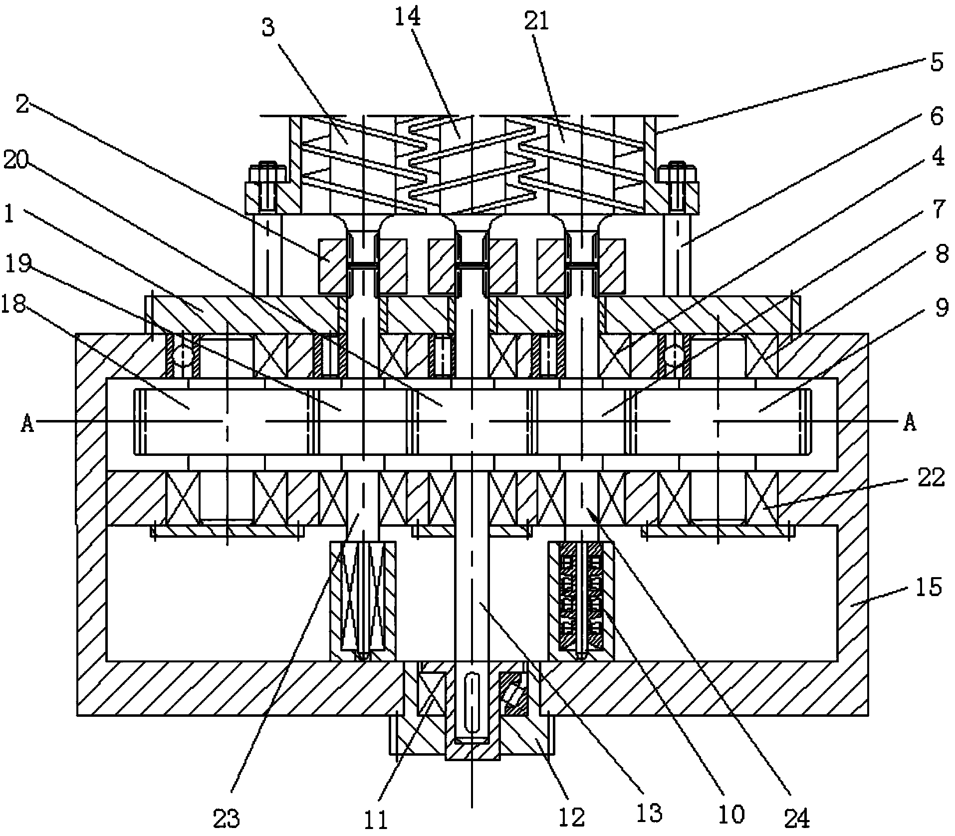
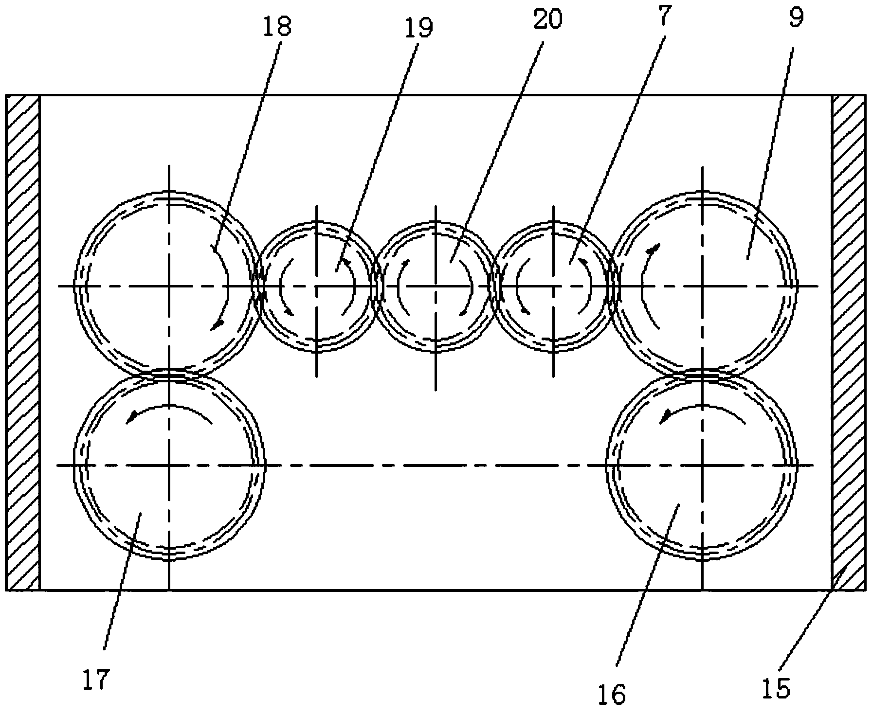
[0020] Such as figure 1 , shown in Fig. 2, a kind of parallel different direction three-screw extruder of the present invention comprises left-handed screw 3, left-handed screw 21, right-handed screw 14, machine barrel 5 and casing 15, wherein: machine barrel 5 is connected by machine barrel The rod 6 is connected with the connecting sealing plate 1, and the connecting sealing plate 1 is fixed on the box body 15 to form the main structure of the three-screw extruder. The left-handed screw 3, the left-handed screw 21, and the right-handed screw 14 are arranged in parallel in the barrel 5, and the three parallel screws are respectively connected to the corresponding gears in a middle output gear 20, an outer output gear 7, and an outer output gear 19 through an inner spline sleeve 2. Sh...


PUM


Abstract

The invention relates to a parallel counter-rotating triple-screw extruder, and belongs to the technical field of plastic extrusion molding equipment. The parallel counter-rotating triple-screw extruder comprises screws, a barrel and a case, wherein the barrel is connected with a connection closing plate through a barrel connecting rod, and the connection closing plate is fixed to the case; three parallel screws are respectively connected with corresponding gear shafts of an middle output gear and two outer output gears through an internal splined hub; the spiral direction of two outer screws of the three parallel screws is opposite to that of the middle screw, and spirals of the screws are engaged; two sides of a middle output gear are respectively engaged with an outer output gear, and outer sides of two outer output gears are respectively engaged with a transition gear; the centers of the middle output gear, the outer output gears and the transition gear are in the same line, and two input gears are respectively engaged with two transition gears; a shaft end of the middle output gear is fixed to the bottom of the case through a radial thrust bearing, and shaft ends of the two outer output gears are arranged on the bottom of the case through a serial antithrust bearing component; and the two transition gears are arranged on the case through a ball bearing, and a shaft of the middle output gear and shafts of the outer output gears are arranged on the case through a needle bearing.

Description

technical field [0001] The invention relates to the technical field of processing machinery related to polymer materials, in particular to a screw extruder for mixing, dispersing and plasticizing polymer materials. Background technique [0002] At present, the most widely used machine for processing polymer materials is the screw extruder. According to the number of screws, it can be divided into single-screw, twin-screw and multi-screw extruders. Because of its simple structure and reliable operation, single-screw extruders are widely used in conventional polymer material processing. With the emergence of new synthetic materials, single-screw extruders cannot meet the process requirements for processing high-temperature, flame-retardant, and high-strength composite materials. Twin-screw extruders with better mixing, plasticizing and dispersing are required. The twin-screw extruder has the advantages of less heat generated by friction, uniform shearing of materials, large s...

Claims


Application Information

Patent Timeline
Patent Type & Authority Patents(China)
IPC IPC(8): B29C47/00B29C47/08B29C47/40B29C47/60F16H1/20B29C48/405B29C48/41
CPCB29C47/40B29C48/41B29C48/405
Inventor 覃伟明
Owner BEN HAO PLASTIC MACHINERY CO LTD
Learn More