Projection optical engine

A projection optics and engine technology, applied in optics, optical components, lenses, etc., can solve the problems of single-chip LED light waves not being well matched, increasing the light output of LED projection light sources, and the difficulty of manufacturing color-combining prisms, etc., to achieve Low cost, good color rendition, and the effect of increasing manufacturing costs

Inactive Publication Date: 2010-12-29
SHENZHEN ESTAR DISPLAYTECH
View PDF9 Cites 6 Cited by
  • Summary
  • Abstract
  • Description
  • Claims
  • Application Information

AI Technical Summary

Problems solved by technology

[0005] However, the LED projection light source has the following disadvantages: 1. The power of single-chip LED is small, and the light output is small; it is necessary to use multiple splicing methods and multi-chip LEDs, such as multi-chip LED arrays, to increase the light output of LED projection light sources
2. The light waves emitted by single-chip LEDs cannot be well matched with the lighting of LCOS screens without CF film
The "bottleneck" of light efficiency of this type of projection optical engine lies in the light rate of various optical components. Generally, the transmittance of optical components used for projection is required to be 90% higher. It is not difficult to imagine that if more optical components are used, the final light The greater the loss, the smaller the overall light rate of the optical engine, and it is more difficult to manufacture the color-combining prism, and the manufacturing cost is higher. The light rate of the color-combining prism is small, and the good point is only 85%.

Method used


Image

  • Projection optical engine
  • Projection optical engine
  • Projection optical engine

Examples


Embodiment Construction

[0041] A projection optical engine provided by the technical solution will be described below in combination with embodiments.

[0042] The present invention is implemented like this:

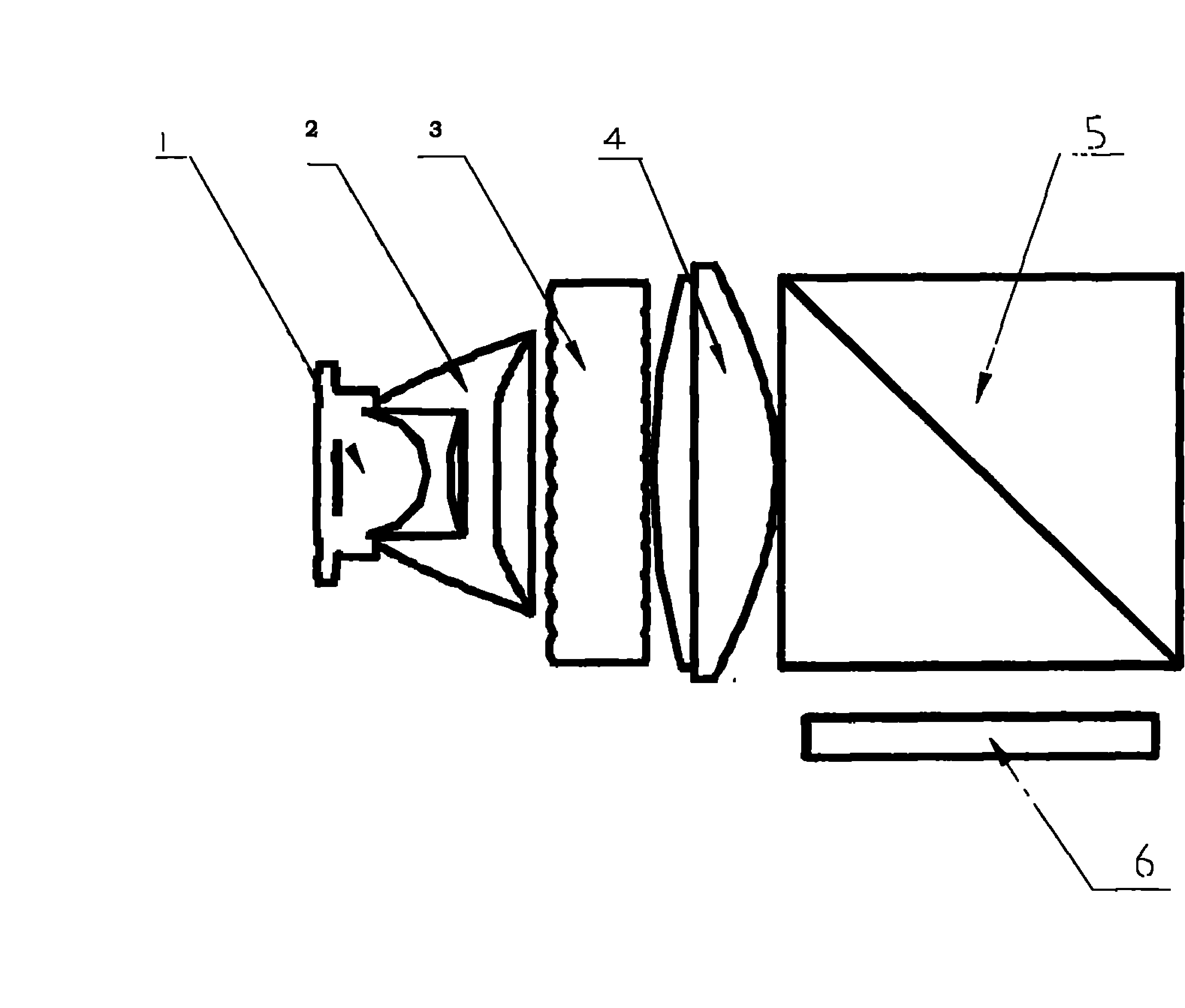
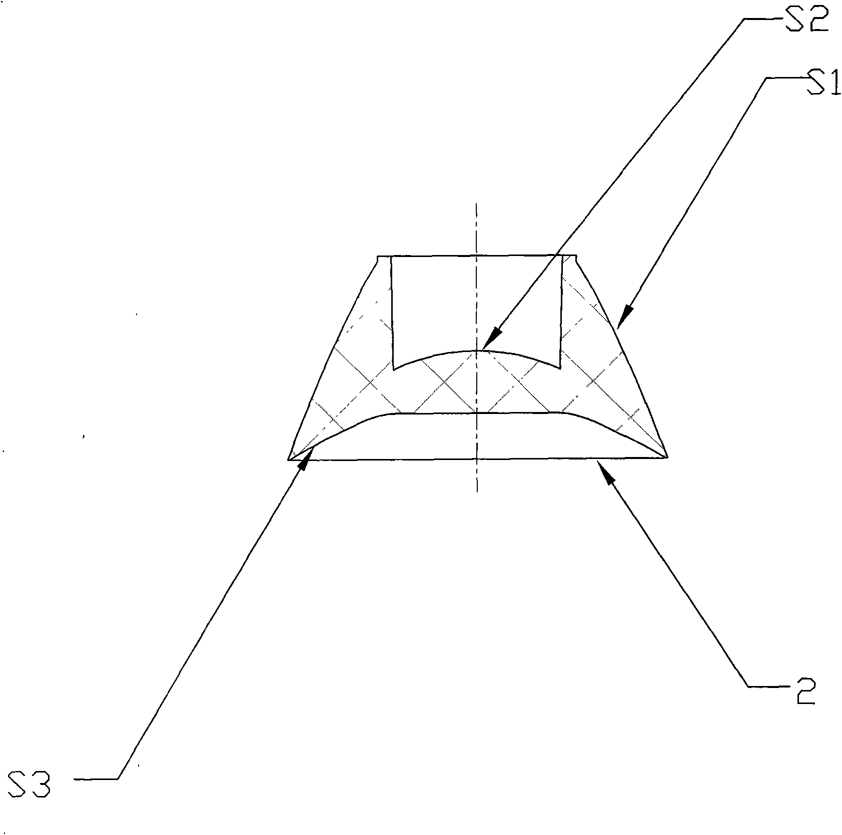
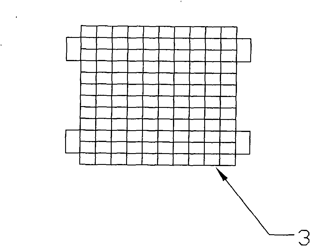
[0043] exist Figure 1 to Figure 5Among them, a projection light source and its projection engine include a single RGB multi-chip LED, a collection of color-combining plastic lenses, a fly-eye lens array, a collimating mirror, a PBS prism, and an imaging device LCOS screen; in a single RGB multi-chip LED, As a light source in the projection optical engine, the three-primary color light emitted by a single RGB multi-chip LED is the main one, and the mixed light beam supplemented by the colored light reaches the fly-eye lens array, which subdivides the discrete light beams emitted by different LEDs into tens to hundreds of small Beam, the collimating mirror changes the optical axis of each small beam to the center of the LCOS screen, so that each small beam is superimposed on the LCOS screen one...


PUM

PropertyMeasurementUnit
Wavelengthaaaaaaaaaa

Abstract

The invention relates to a projection light source, a projection optical system and projection display equipment, in particular to a projection optical engine. The light source is a single RGB multi-chip LED; the front end of the single RGB multi-chip LED is provided with a collecting and color combining plastic lens; the front end of the collecting and color combining plastic lens is provided with a fly-eye lens array which subdivides discrete light beams out of an emergent part into tens of to hundreds of small light beams; a collimation lens is arranged between the front end of the fly-eye lens array and an LCOS screen not provided with a CF film, and changes the optical axis of each small light beam to the center of the LCOS screen so as to superpose each small light beam onto the LCOS screen; and the spectrum of the white light beams lighting the LCOS screen are correspondingly fitted with the LCOS screen reflection spectrum. The projection optical engine has the basic advantages of long service life, short response time, easy drive, no radiation heat, high lighting effect of the light source, energy conservation and environmental protection of the LED projection light source, and also has the advantages of improving light output, brightness uniformity, chroma uniformity and color reproduction rate, and changing color temperature.

Description

technical field [0001] The present invention relates to a projection light source, a projection optical system and a projection display device, in particular to a projection light source of LED arrays with different wavelengths, a projection optical engine using color combination and uniform light vibration shape, and a projection device using the optical engine. Background technique [0002] With the continuous progress of society, science and technology are also constantly advancing. In the video projector industry, metal halide lamps have been used as projection light sources for such front projection devices for a long time; however, LEDs have been used as projection light sources in recent years. [0003] This type of projector is cheap and practical, and the projector can be made smaller. This kind of optical engine can be placed in a mobile phone, and it is welcomed by the market. After switching to LED projection light source, it has the advantages of long life, sho...

Claims


Application Information

Patent Timeline
IPC IPC(8): G03B21/20G02B1/04G02B3/10
Inventor 刘美鸿母林
Owner SHENZHEN ESTAR DISPLAYTECH
Why Eureka
Try Eureka