
PET detector module, PET detector and PET system

A detector, photoelectric detection technology, applied in the fields of radiological diagnosis instruments, medical science, diagnosis, etc., can solve the problems of impossible to provide reflectivity, reduced light collection, etc.

Pending Publication Date: 2020-01-14
SHENYANG INTELLIGENT NEUCLEAR MEDICAL TECH CO LTD
View PDF17 Cites 0 Cited by
  • Summary
  • Abstract
  • Description
  • Claims
  • Application Information

AI Technical Summary

Problems solved by technology

The disadvantage of the above solution is that none of the reflective materials currently used can provide 100% reflectivity. When photons are reflected multiple times on the surface, a large number of photons will be absorbed by the reflective layer, resulting in a decrease in light collection.

Method used


Image

  • PET detector module, PET detector and PET system
  • PET detector module, PET detector and PET system
  • PET detector module, PET detector and PET system

Examples


Embodiment Construction

[0034] Reference will now be made in detail to the exemplary embodiments, examples of which are illustrated in the accompanying drawings. When the following description refers to the accompanying drawings, the same numerals in different drawings refer to the same or similar elements unless otherwise indicated. Embodiments described in the following exemplary embodiments do not represent all embodiments consistent with the present application. Rather, they are merely examples of apparatuses and methods consistent with aspects of the present application as recited in the appended claims.

[0035] The terminology used in this application is for the purpose of describing particular embodiments only, and is not intended to limit the application. As used in this application and the appended claims, the singular forms "a", "the", and "the" are intended to include the plural forms as well, unless the context clearly dictates otherwise.

[0036] It should be understood that "first", ...


PUM

PropertyMeasurementUnit
transmittivityaaaaaaaaaa
refractive indexaaaaaaaaaa

Abstract

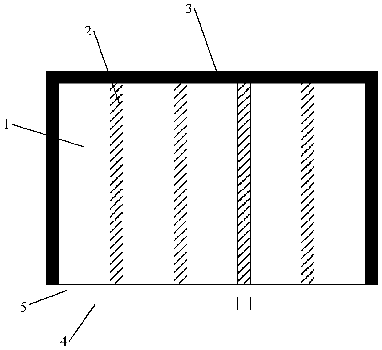
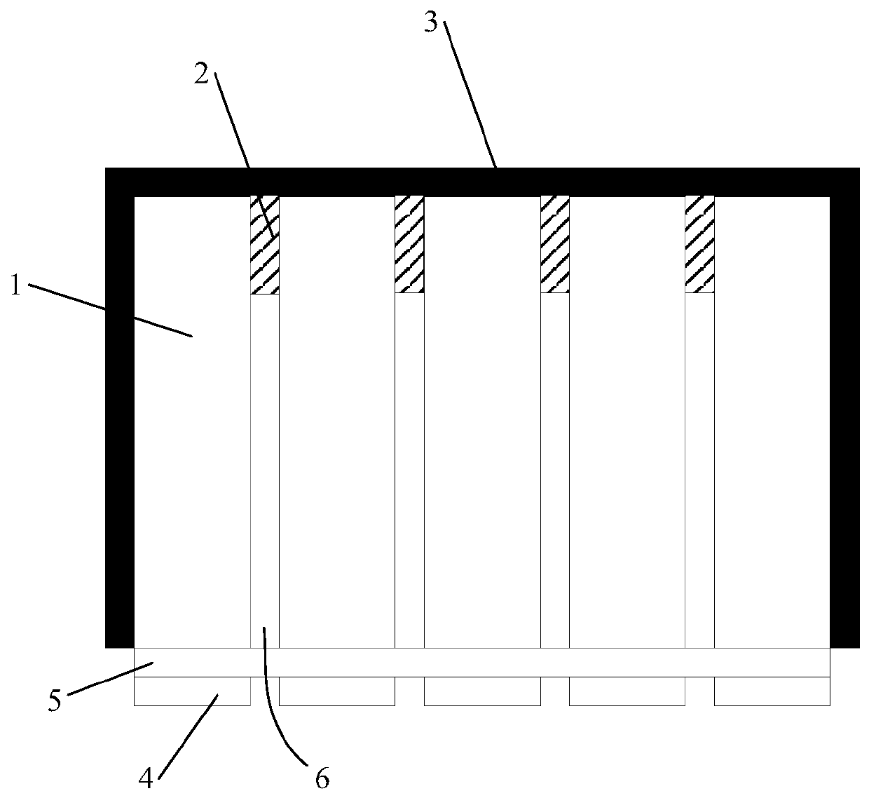
The invention discloses a PET detector module, a PET detector and a PET system. The PET detector module comprises an array formed by a plurality of crystal. In the array, at least part of adjacent crystal is adhered through high-transparency optical cement, and the refractive index of the optical cement is less than that of the crystal. Since adjacent crystal is adhered through the high-transparency optical cement, the refractive rate of the high-transparency optical cement is less than that of the crystal, compared with a mode of adding a high-reflection material among crystal, use of the high-transparency optical cement has the advantage that light can perform total reflection on the interface formed by the crystal and a high-transparency optical cement layer, and total reflection does not have photon loss, but when a high-reflection layer material is used, the reflective rate of the high-reflection layer material cannot reach 100 percent, and more photons are lost after multiple times of reflection. Furthermore, the selected optical cement has high light transmittance, photon transmittance through the optical cement layer causes less light loss, therefore, the PET detector module can be used for improving light collection, and more photons can be detected.

Description

technical field [0001] The present application relates to the technical field of positron emission tomography, in particular to a PET detector module, a PET detector and a PET system. Background technique [0002] Positron emission tomography (PET) is a nuclear medicine detector used to observe the body's metabolism. The principle is to inject isotope-labeled drugs (imaging agents) with positron emission into the human body. These drugs participate in the physiological processes of the human body. The annihilation effect occurs during the metabolic process, generating two back-to-back gamma rays with an energy of 0.511 MeV. After γ interacts in the scintillator, a large number of photons are released, which are detected by the back-end photodetection element. The more photons are detected, the more conducive to improving the performance of the detector. [0003] In order to accurately locate the incident position of γ in the current PET system, the crystal shape is generall...

Claims


Application Information

Patent Timeline
Patent Type & Authority Applications(China)
IPC IPC(8): A61B6/03
CPCA61B6/037A61B6/4258
Inventor 李新颖梁国栋王希赵健徐保伟
Owner SHENYANG INTELLIGENT NEUCLEAR MEDICAL TECH CO LTD
Learn More