Motor generator unit

A technology of motor generators and brushes, which is applied in the direction of electromechanical devices, electric components, electrical components, etc., can solve problems such as excessive moisture, and achieve the effect of realizing wiring and rationalization

Active Publication Date: 2010-12-22
MITSUBISHI ELECTRIC CORP
View PDF2 Cites 0 Cited by
  • Summary
  • Abstract
  • Description
  • Claims
  • Application Information

AI Technical Summary

Problems solved by technology

[0010] It is not mentioned in Patent Document 1 that the motor generator unit integrating the motor generator and the inverter unit is installed near the engine such as the engine room, but since it is easy to withstand the vibration of the engine and moisture from the outside Therefore, it is necessary to ensure the reliability of the vibration resistance and insulation performance of the wiring connection between the inverter control circuit, the circuit related to the control circuit, and the parts, and it is necessary to rationalize the connection of various wiring in advance. , and in the case of integrating the motor generator with the inverter unit, the control circuit of the inverter and the circuits and components related to the control circuit are easily affected by the magnetic field from the stator and rotor of the motor generator, Therefore it is also necessary to ensure noise resistance performance

Method used


Image

  • Motor generator unit
  • Motor generator unit
  • Motor generator unit

Examples


Embodiment Construction

[0077] Embodiment 1

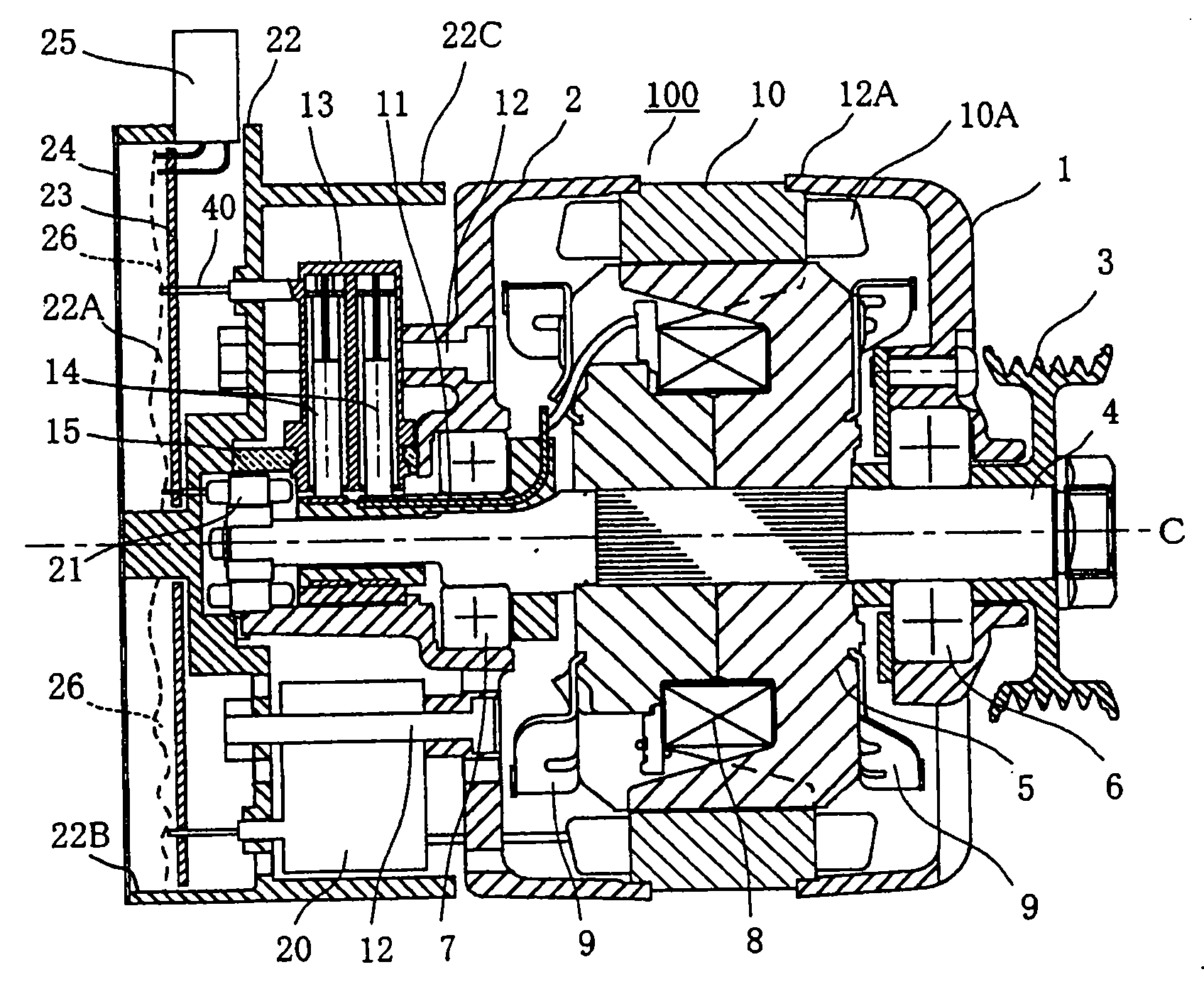
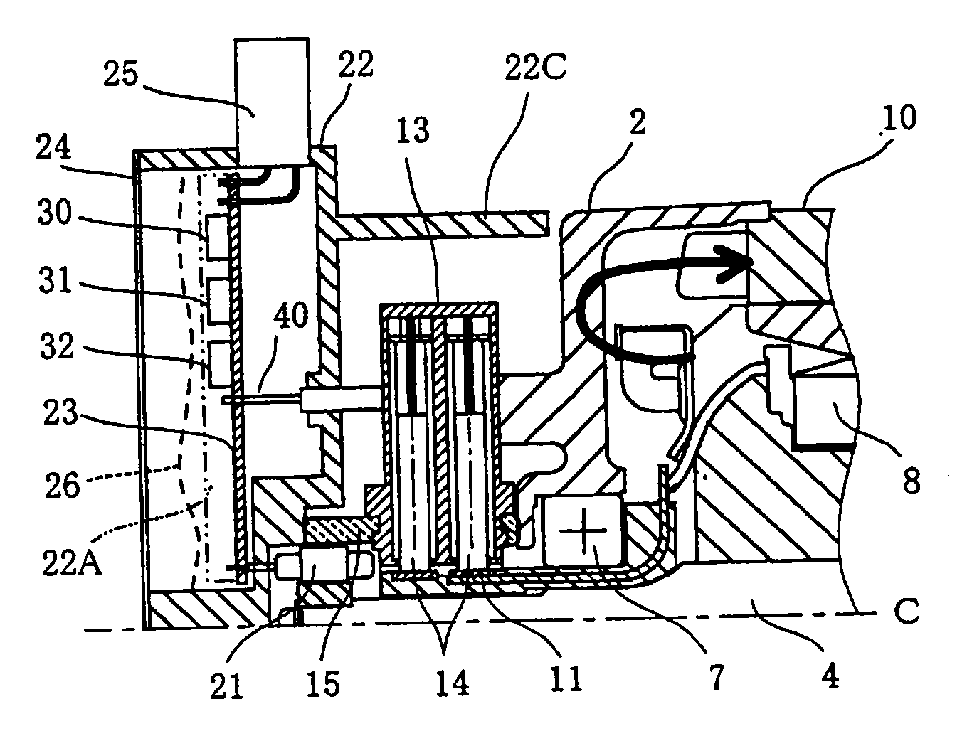
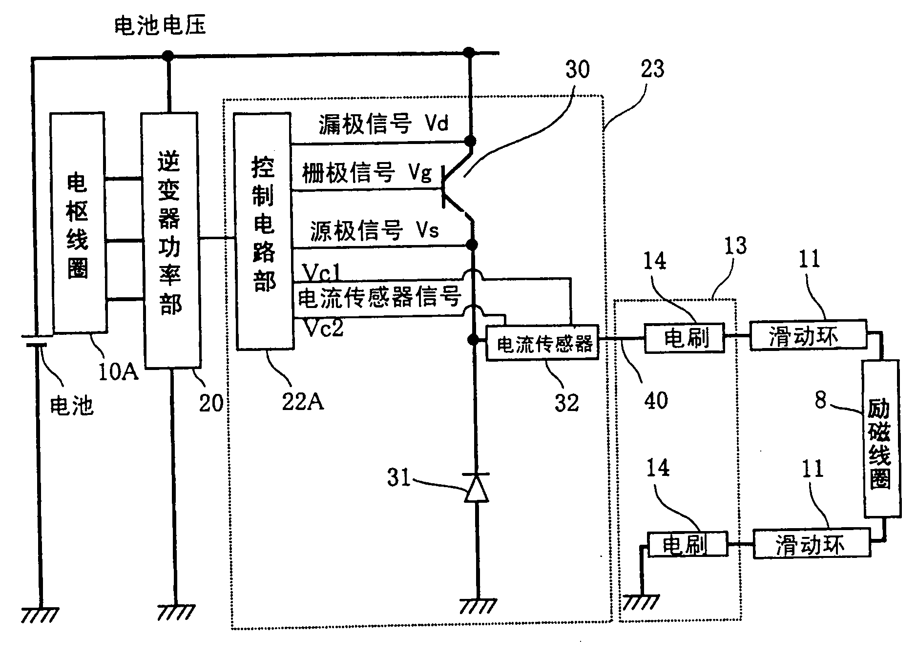
[0078] Below, refer to Figure 1 to Figure 4 Embodiment 1 of the present invention will be described. figure 1 It is a longitudinal sectional side view of an example of a schematic configuration of the entire motor generator device. figure 2 yes means figure 1 A longitudinal sectional side view of a specific example of the structure of the excitation circuit. image 3 It is a wiring diagram mainly showing examples of specific wiring of the field circuit. Figure 4 It is a perspective view of a part of the rotor viewed obliquely from the longitudinal direction of the shaft. The same reference numerals in the drawings denote the same parts.

[0079] First, use figure 1 The general structure of the motor generator will be described.

[0080] That is, in figure 1 Among them, the motor generator has a box 12A composed of an aluminum front bracket 1 and a rear bracket 2, and is installed in the box 12. On one end of the extension direction of the a...


PUM


Abstract

A motor generator main body 100 includes: field winding 8 whose energization is controlled by a semiconductor control device 30 that is supplied with power through a brush 14 and whose energization is controlled by a control circuit unit 22A; and armature winding 10A whose energization is controlled by an inverter power circuit unit 20 controlled by the control circuit unit 22A. The motor generator device is constructed by mounting the inverter power circuit unit 20 and the control circuit unit 22A in the motor generator main body. The brush is provided between the field winding 8 and the armature winding 10A, and the control circuit unit 22A, and the semiconductor control device 30 is mounted in the control circuit mounted portion 22 mounted with the control circuit unit 22A. The motor generator unit tries for integrating the motor generator with the inverter to make the wiring of the energization circuit unit for providing the current to the rotor coil reasonable.

Description

[0001] This application is a divisional application of an invention patent application with an application date of December 27, 2005, an application number of 200510138146.3, and an invention title of "motor generator device". [0002] technology area [0003] The present invention relates to a motor generator having an excitation coil controlled by a semiconductor control element that is fed through brushes and controlled by a control circuit unit, and an inverter controlled by the control circuit unit. The inverter power circuit unit and the control circuit unit are mounted on the motor generator main body of the armature coil that controls the energization of the inverter power circuit unit. Background technique [0004] Conventional AC motor generators for vehicles are generally arranged laterally outside the engine as shown in Japanese Patent Application Laid-Open No. 2001-95103 (Patent Document 1), and are connected to the engine by a belt and a pulley to drive the motor...

Claims


Application Information

Patent Timeline
Patent Type & Authority Applications(China)
IPC IPC(8): H02K13/00H02K11/00H02K5/14
CPCH02K5/141H02K11/048H02K11/05
Inventor 矶田仁志浅尾淑人加藤政纪秋田裕之
Owner MITSUBISHI ELECTRIC CORP
Why Eureka
Try Eureka