Loop heat pipes for solar energy water heater

A technology of solar water heater and loop heat pipe, applied in the field of solar heat pipe, can solve the problems of reducing transmission power, affecting the diameter of steam chamber, complicated manufacturing process, etc., and achieving the effect of increasing transmission power, solving single installation and wide application.

Inactive Publication Date: 2010-12-22
JIANGSU HETE ENERGY CONSERVATION & ENVIROMENTAL PROTECTION CO LTD
View PDF9 Cites 0 Cited by
  • Summary
  • Abstract
  • Description
  • Claims
  • Application Information

AI Technical Summary

Problems solved by technology

Conventional horizontal heat pipes have no directionality in use and can operate in a horizontal state. However, due to the use of a liquid-absorbing core structure, the structure is complicated and the manufacturing process is cumbersome. At the same time, the structure of the liquid-absorbing core affects the diameter of its vapor chamber, causing its Reduced power makes it difficult to meet actual production needs

Method used


Image

  • Loop heat pipes for solar energy water heater
  • Loop heat pipes for solar energy water heater
  • Loop heat pipes for solar energy water heater

Examples


Embodiment 1

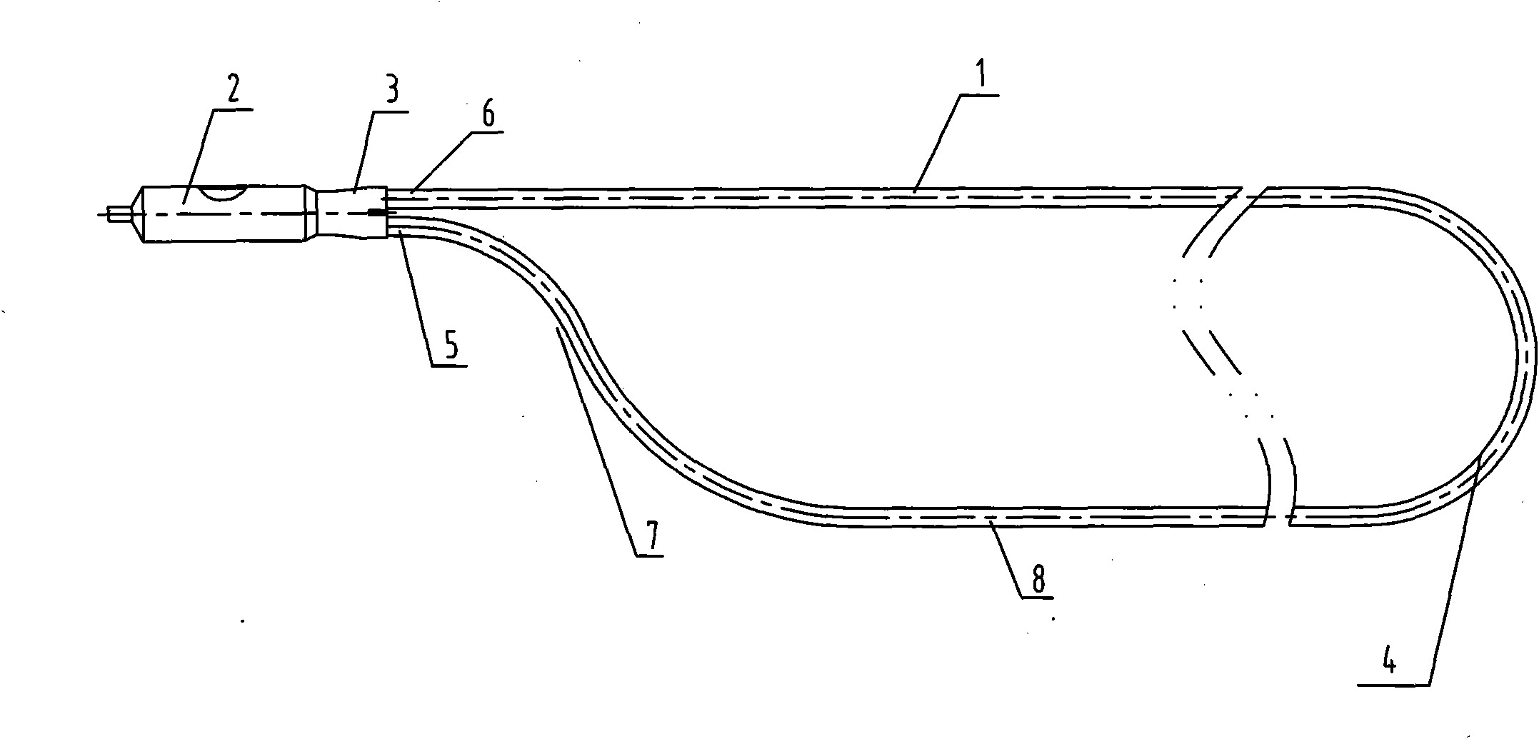
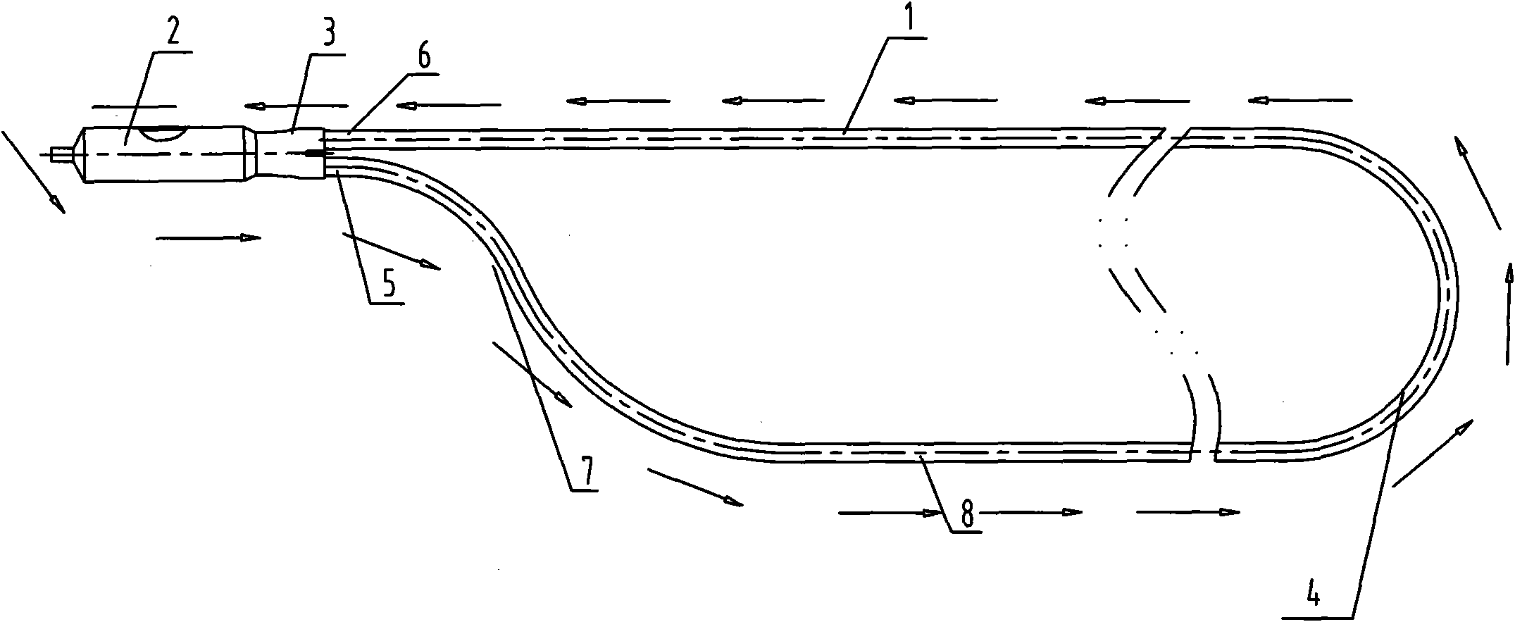
[0020] This embodiment is a loop heat pipe for a solar water heater, with a structure such as figure 1 As shown, it includes evaporating section 1, condensing section 2 and adiabatic section 3. The adiabatic section 3 is located between evaporating section 1 and condensing section 2. Working medium is provided in the heat pipe shell of evaporating section 1. Evaporating section 1 is composed of two sections of tubes. The road is connected into a loop pipe through a section of semi-circular arc pipe 4. The front section of the evaporation section 1 has a narrower structure than the middle section and the back section of the evaporation section. The two pipelines in the front section of the evaporation section 1 are connected to the adiabatic section 3 through the vapor working medium outlet 6 and the liquid working medium inlet 5 near the adiabatic section, and the two pipelines of the evaporation section 1 are connected to the pipeline of the vapor working medium outlet 6 The...

Embodiment 2

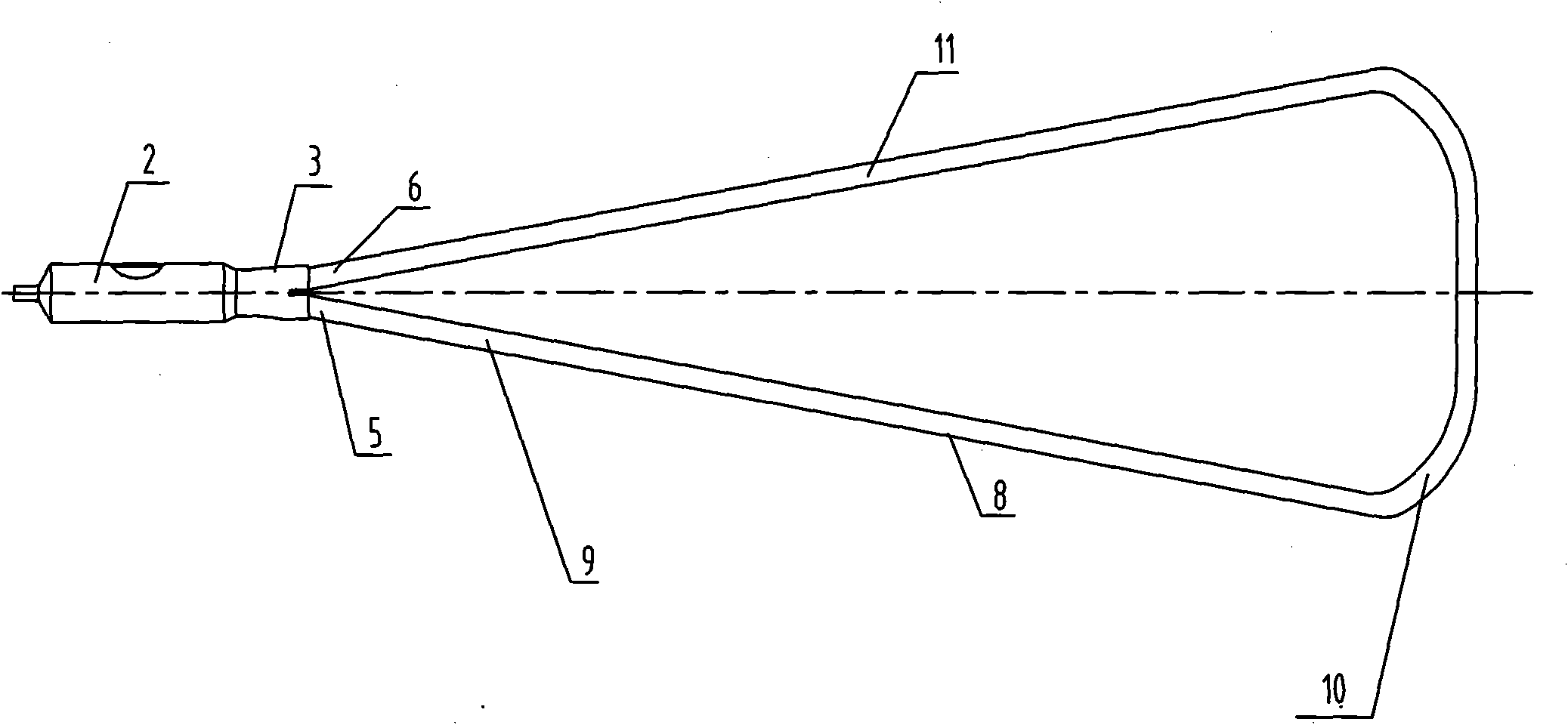
[0023] This embodiment is another kind of structural loop heat pipe for solar water heaters, the structure is as image 3 As shown, the principle of this embodiment is the same as that of Embodiment 1, and the difference in structure is that the liquid working medium inlet 5 of the evaporating section 1 is connected to the arc tube 10 through a downwardly inclined straight tube 9, and the arc tube 10 is connected with a vapor tube. The downward-sloping straight pipe 11 of the state working medium outlet 6 has a conical cross-section in the entire evaporation section. In the evaporating section 1, the heat pipe with the vapor working medium outlet 6 is an inclined straight pipe 11, and the heat pipe with the liquid working medium inlet 5 in the other section is also an inclined straight pipe 9, which is conducive to the smoother flow of the vapor working medium. The heat transfer capacity of the heat pipe is increased. The arc tube 10 is used to connect the elbow, which streng...


PUM

PropertyMeasurementUnit
Meshaaaaaaaaaa

Abstract

The invention relates to solar energy heat pipes, in particular to loop heat pipes for a solar energy water heater, comprising an evaporation section, a condensation section and a heat insulation section, wherein the heat insulation section is arranged between the evaporation section and the condensation section, the shells of heat pipes in the evaporation section are internally provided with a working medium, the evaporation section is a loop pipe which is formed by connecting two sections of pipes via a bent pipe, a narrower structure compared with the middle section and the back section of the evaporation section is arranged between the two sections of the pipes of the front section of the evaporation section, the two sections of the pipes of the front section of the evaporation section converge in the heat insulation section by a vaporous working medium outlet and a liquid working medium inlet at a position closing to the heat insulation section, the two sections of the pipes of the evaporation section are connected to a position corresponding to a pipe of the vaporous working medium outlet and a position corresponding to the pipe of the liquid working medium inlet, and a pipeline at the rear part of the liquid working medium inlet of the evaporation section is provided with a structure inclining downwards. The heat pipes of the invention strengthen the evaporation and condensation processes of the working medium inside the heat pipes, thereby not only increasing transmitted power of the heat pipes at a small angle of inclination and at the level, but also solving the defect of single installation of the solar energy water heater.

Description

technical field [0001] The invention relates to a solar heat pipe, in particular to a loop heat pipe for a solar water heater. Background technique [0002] At present, for heat pipe collectors in solar water heating systems, there are many limitations in the use of two-phase closed thermosiphons and conventional horizontal heat pipes on the market. The two-phase closed thermosiphon has no liquid-absorbing core inside, and the manufacturing process is simple. The work of the working fluid is only through the action of gravity to complete the entire working process and realize the heat absorption and heat release of the heat pipe. However, gravity has directionality. Therefore, the two-phase closed thermosiphon that only relies on gravity to realize the circulation of the working fluid must meet a certain inclination angle in installation, and it cannot operate in a horizontal state, which has great limitations. In the conventional horizontal heat pipes commonly used at pres...

Claims


Application Information

Patent Timeline
IPC IPC(8): F24J2/46F24J2/32F24S10/95
CPCF24J2/32Y02E10/44F28D15/0266F24S10/95
Inventor 庄骏龙倩文
Owner JIANGSU HETE ENERGY CONSERVATION & ENVIROMENTAL PROTECTION CO LTD
Why Eureka
Try Eureka