Divided-flow vacuum pump unit water cooling device

A technology of water cooling device and vacuum pump, applied in the direction of variable capacity pump components, liquid variable capacity machinery, pump components, etc., can solve the problems of vacuum pump burnout, waste of water resources, shortening the service life of vacuum pump, etc., to prevent overheating and burning damage, saving water resources and prolonging the service life

Active Publication Date: 2010-12-22
EGING PHOTOVOLTAIC TECHNOLOGY CO LTD
View PDF6 Cites 3 Cited by
  • Summary
  • Abstract
  • Description
  • Claims
  • Application Information

AI Technical Summary

Problems solved by technology

Otherwise, the vacuum pump will heat up rapidly, and in severe cases, it will cause the vacuum pump to burn out and reduce the service life of the vacuum pump.
[0003] In the solar cell module production workshop, many devices need to use vacuum, so a vacuum pump room must be equipped to provide vacuum services for the entire battery assembly workshop. The vacuum pump room is composed of several vacuum pumps. In order to ensure that the vacuum pumps can work normally, each vacuum pump must be equipped with Independent water cooling system, that is, each vacuum pump must be equipped with a cooling water inlet pipe and a hot water outlet pipe, so the vacuum pump machine room consumes a large amount of cooling water, not only high operating costs, but also a serious waste of water resources

Method used


Image

  • Divided-flow vacuum pump unit water cooling device
  • Divided-flow vacuum pump unit water cooling device
  • Divided-flow vacuum pump unit water cooling device

Examples


Embodiment Construction

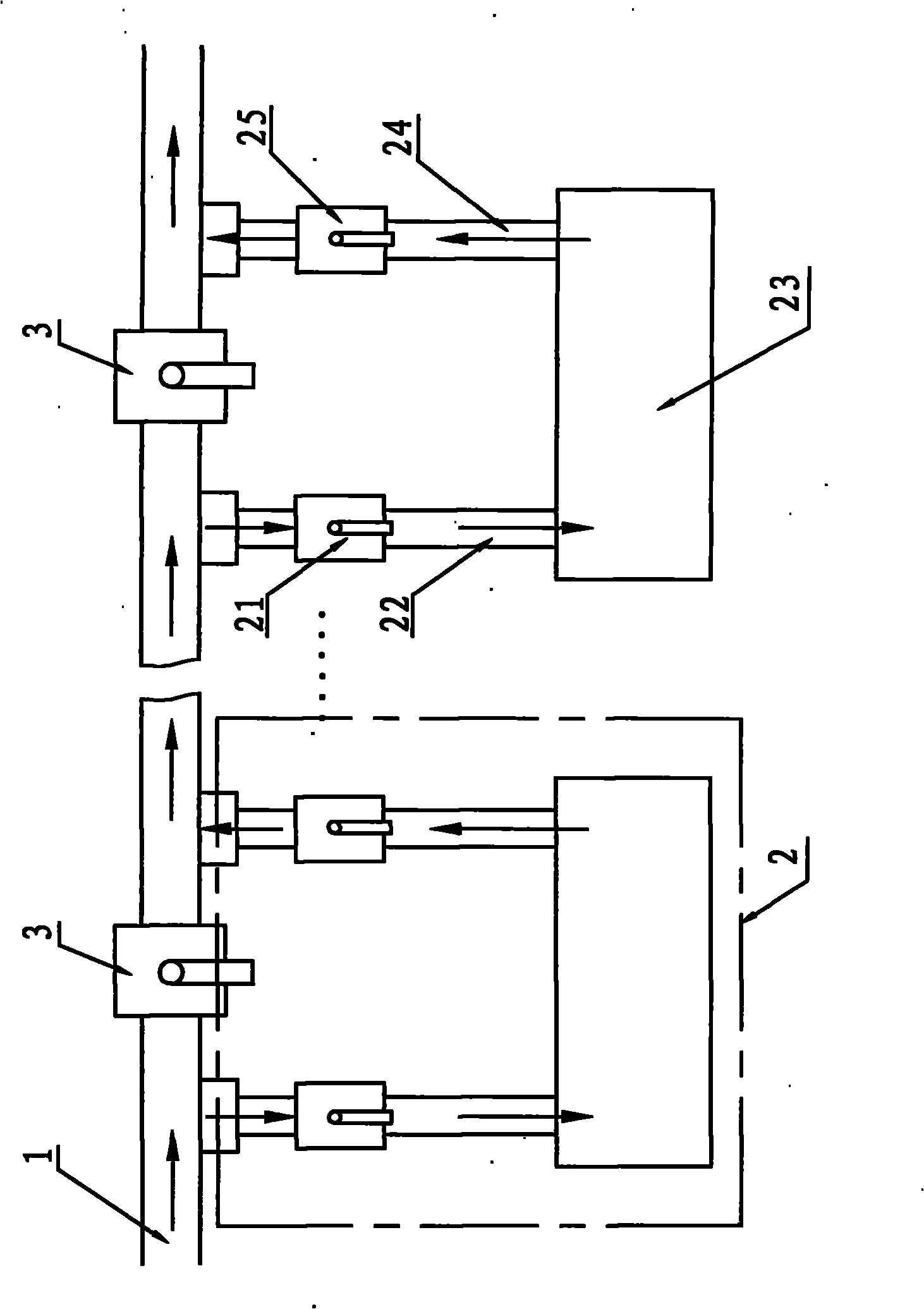
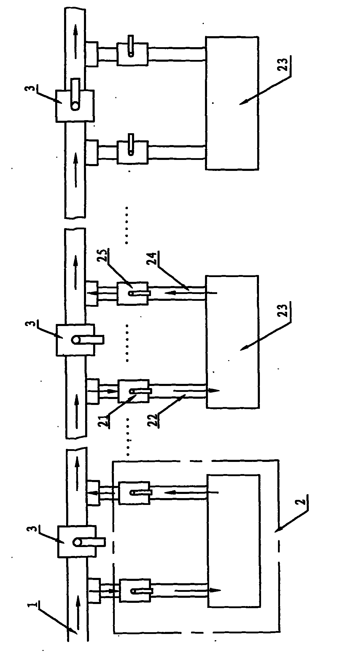
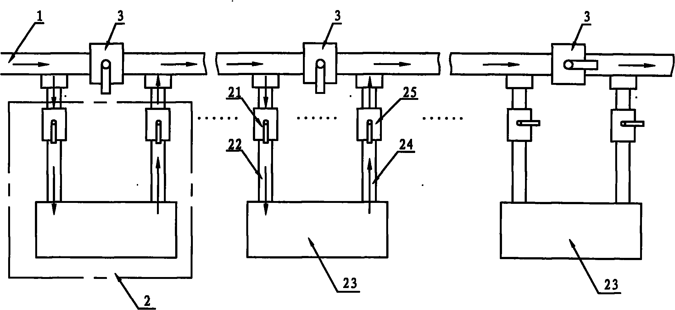
[0014] The water cooling device of the split flow vacuum pump unit, such as figure 1 As shown in ~3, it includes a main water inlet pipe 1, several vacuum pump cooling units 2 and several main control valves 3, all vacuum pump cooling units 2 are connected to the main water inlet pipe 1 in turn, and each vacuum pump cooling unit 2 All are composed of water inlet branch valve 21, water inlet branch pipe 22, vacuum pump 23, water outlet branch pipe 24 and water outlet branch valve 25, water inlet branch pipe 22 is connected to main water inlet pipe 1 through water inlet branch valve 21 , the water outlet branch pipe 24 is connected to the main water inlet pipe 1 through the water outlet branch valve 25, the water inlet branch pipe 22 and the water outlet branch pipe 24 are connected to the cooling water cavity of the vacuum pump 23, and the main control valve 3 is installed in series On the main water inlet pipe 1 , and each main control valve 3 is arranged between the connectio...


PUM


Abstract

The invention relates to a divided-flow vacuum pump unit water cooling device which comprises a main water inlet pipe, a plurality of vacuum pump cooling units and a main control valve. Each vacuum pump cooling unit comprises a water inlet branch valve, a water inlet branch pipe, a vacuum pump, a water outlet branch pipe and a water outlet branch valve. The water inlet branch pipe is connected on the main water inlet pipe through the water inlet branch valve, the water outlet branch pipe is connected on the main water inlet pipe through the water outlet branch valve, and the main control valve is arranged between the water inlet branch pipe and a joint of the water outlet branch pipe and the main water inlet pipe. Compared with the prior art, the cooling water quantity consumed by the vacuum pump cooling device with the structure is saved by 60-70% on the premise of ensuring the normal work of the vacuum pump; and not only can the increased temperature of the vacuum pump be ensured to be lower than the standardized operating temperature of the vacuum pump, but also water resources are greatly saved.

Description

Technical field: [0001] The invention relates to a cooling device of a vacuum pump unit, in particular to a cooling device of a split-flow vacuum pump unit. Background technique: [0002] Rotary vane vacuum pump is one of the most basic vacuum obtaining equipment in vacuum technology. Rotary vane vacuum pumps are mostly small and medium-sized pumps, which can be divided into single-stage and double-stage. The so-called two-stage is to connect two single-stage pumps in series in structure. Bipolar rotary vane vacuum pump (commonly known as 2X vacuum pump) is the basic equipment used to pump out the gas in a specific sealed container, so that the container can obtain a certain degree of vacuum. The vacuum degree of the double-stage vacuum pump of the same specification is higher than that of the single-stage. Two-stage rotary vane pump can directly obtain 6.0×10 -2 The vacuum degree below Pa can be used as a backing pump for other vacuum equipment, and can be used for meta...

Claims


Application Information

Patent Timeline
Patent Type & Authority Applications(China)
IPC IPC(8): F04B39/06
Inventor 周锦慧
Owner EGING PHOTOVOLTAIC TECHNOLOGY CO LTD
Why Eureka
Try Eureka