
Intake and exhaust integrated pulse valve

An integrated, pulse valve technology, applied to the separation of dispersed particles, chemical instruments and methods, and filtration of dispersed particles, which can solve problems such as inability to supply gas

Inactive Publication Date: 2010-12-22
WUXI HUAXING ELECTRIC POWER ENVIRONMENTAL PROTECTION REPAIRING & MFG
View PDF5 Cites 3 Cited by
  • Summary
  • Abstract
  • Description
  • Claims
  • Application Information

AI Technical Summary

Problems solved by technology

[0003] The working process of the original electromagnetic pulse valve: the ordinary electromagnetic pulse valve has to exhaust but not supply air

Method used


Image

  • Intake and exhaust integrated pulse valve
  • Intake and exhaust integrated pulse valve

Examples


Embodiment Construction

[0012] The present invention will be further described below in conjunction with specific drawings and embodiments.

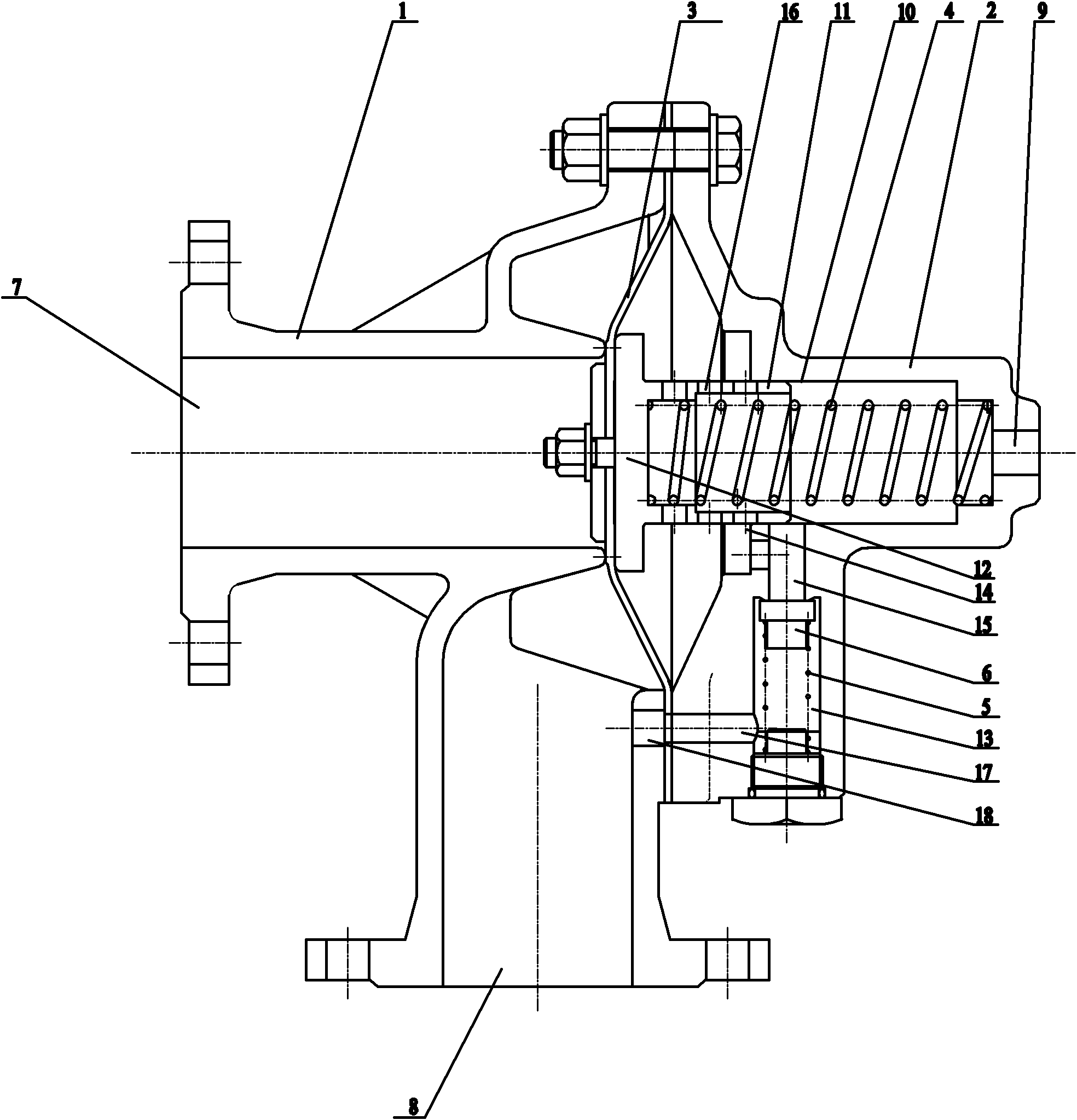
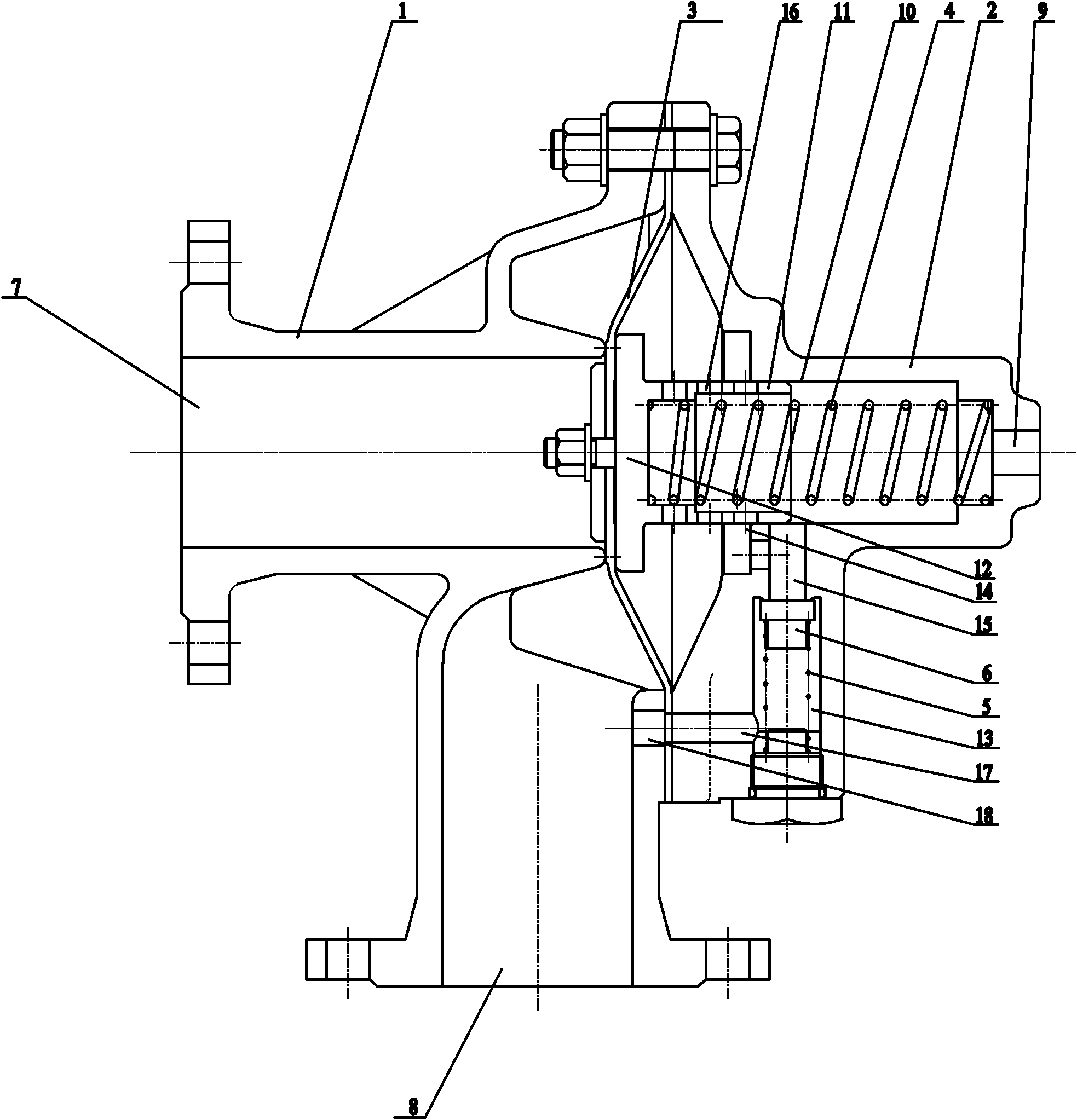
[0013] As shown in the figure: the intake and exhaust integrated pulse valve includes fixedly installed left valve body 1, right valve body 2 and sealing diaphragm 3, and the left valve body 1 is provided with a compressed air outlet port 7 and a container end port 8 , the right valve body 2 is provided with a compressed air inlet port 9, and the left valve body 1 and the right valve body 2 will press the edge of the sealing diaphragm 3 tightly; The air inlet port 9 is connected, and a spring seat tube 11 is slidably connected in the sliding hole 10. The first return spring 4 is arranged in the spring seat tube 11, and the right end of the first return spring 4 is offset against the right valve body 2; The left end of the pipe 11 is fixedly connected with a sealing top plate 12, the middle part of the sealing diaphragm 3 is fixed on the sealing top plate 12, an...


PUM


Abstract

The invention relates to an intake and exhaust integrated pulse valve. A compressed air outlet connector and a container-end connector are arranged on a left valve body; a compressed air inlet connector is arranged on a right valve body; the edge part of a sealing diaphragm is tightly pressed by the left valve body and the right valve body; a sliding hole is formed in the right valve body and communicated with the compressed air inlet connector; a spring seat pipe, in which a first return spring is arranged, is connected in the sliding hole in a sliding manner; a sealing top plate is fixedly connected to the left end part of the spring seat pipe; the middle part of the sealing diaphragm is fixed on the sealing top plate, so that the sealing top plate, along with the sealing diaphragm, can be propped against the left valve body, so as to cut off the gas channel of the compressed air outlet connector; and a one-way switch hole, in which a second return spring and a sealing pressing block are arranged, is formed in the right valve body. Therefore, only one valve is needed to finish intake and exhaust, and control points are fewer during the operation, and the valve does not need to be pneumatically or electrically driven.

Description

technical field [0001] The invention relates to a gas valve, in particular to an intake and exhaust integrated pulse valve. Background technique [0002] The electromagnetic pulse valve can be used for the intake and discharge valve of the air cannon arch breaker of the bin body or the pulse injection valve of the air box bag filter. [0003] The working process of the original electromagnetic pulse valve: the ordinary electromagnetic pulse valve has to exhaust but not supply air. [0004] There is a problem with the original pulse valve: the ordinary electromagnetic pulse valve is used in the air cannon arch breaker. It needs to install another intake valve. Purpose, to achieve this purpose, the valve pulse valve in the prior art needs two control points: one is an electromagnetic pulse valve for exhaust; the other is an electric or pneumatic control valve for air intake. Contents of the invention [0005] The object of the present invention is to overcome the deficienc...

Claims


Application Information

Patent Timeline
Patent Type & Authority Applications(China)
IPC IPC(8): B01D46/04B01D46/42
Inventor 吴浩仑杨青
Owner WUXI HUAXING ELECTRIC POWER ENVIRONMENTAL PROTECTION REPAIRING & MFG
Learn More