
Method for replacing stopper rod on line for tundish and cross arm structure for replacing stopper rod

A technology of tundish and cross arm, which is applied in the field of on-line stopper replacement in tundish, which can solve the problems of low cost, low life of stopper, difficulty in pouring, etc., and achieve the effect of reducing pouring cost, strong operability and reasonable design

Inactive Publication Date: 2010-12-15
杭州钢铁股份有限公司 +1
View PDF2 Cites 2 Cited by
  • Summary
  • Abstract
  • Description
  • Claims
  • Application Information

AI Technical Summary

Problems solved by technology

The stopper type can pour high-quality molten steel but the cost is high; the sizing nozzle type has low cost but is not easy to pour high-quality molten steel; the stopper variable-diameter nozzle type combines the advantages of the stopper type and the sizing nozzle type, but its disadvantages are When pouring, the stopper hangs in the molten steel and is more severely scoured by the eddy current of the molten steel than the nozzle, so that the life of the stopper is lower than the life of the nozzle. To realize the pouring of high-quality molten steel, the tundish age is controlled by the life of the stopper, and the result is that the pouring cost cannot be further reduced

Method used


Image

  • Method for replacing stopper rod on line for tundish and cross arm structure for replacing stopper rod
  • Method for replacing stopper rod on line for tundish and cross arm structure for replacing stopper rod
  • Method for replacing stopper rod on line for tundish and cross arm structure for replacing stopper rod

Examples


Embodiment

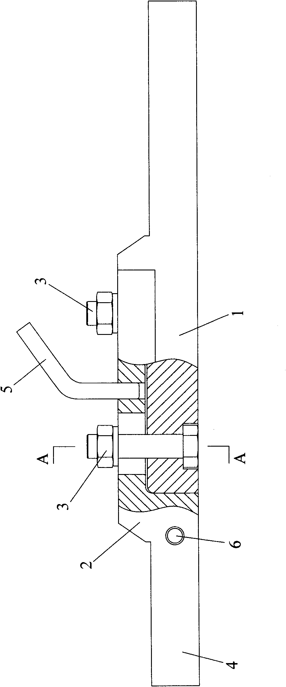
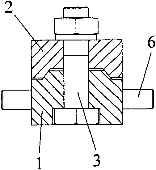
[0014] Example: see Figure 1-3 , the present invention connects and arranges the movable cross arm 2 on the fixed cross arm 1, the end of the movable cross arm 2 is provided with a fork 4 for clamping the stopper rod, and the connecting part of the movable cross arm 2 and the connection of the fixed cross arm 1 The upper and lower parts of the cross arm are superimposed, and the connecting part of the movable cross arm is arranged on the top of the connecting part of the fixed cross arm, and the bolts 3 are used to fix the two together. The connecting part of the movable cross arm 2 is provided with a handle 5, and the The base of the fork is provided with a pin 6 for limiting the stopper rod.

[0015] The method for on-line replacement of the stopper rod in the tundish of the present invention is as follows: a. After the fork of the movable cross arm and the end of the stopper rod are assembled, put them into a baking oven for baking; b. Put the baked stopper rod on a cart ...


PUM


Abstract

The invention discloses a method for replacing a stopper rod on line for a tundish and a cross arm structure for replacing the stopper rod. The cross arm structure is characterized in that: a movable cross arm is connected on a fixed cross arm, and the end of the movable cross arm is provided with a fork head for blocking the stopper rod. The method for replacing the stopper rod on line mainly comprises the following steps of: after the movable cross arm and the stopper rod are assembled across, baking the movable cross arm and the stopper rod in an oven, and then moving the movable cross arm and the stopper rod to the lower part of a hanger; driving the tundish to a sizing nozzle to adopt sizing control; hoisting the used stopper rod out together with the movable cross arm by using the hanger; hoisting the baked stopper rod into the tundish together with the movable cross arm, and settling the bottom end of the stopper rod to the nozzle of the tundish; and adjusting the stopper rod to control the casting current of the tundish, and screwing down bolts for connecting the movable cross arm and the fixed cross arm to finish on-line replacement of the stopper rod. The service lives of the stopper rod and the nozzle can be matched, the casting cost is reduced, the service life of the tundish for casting high-quality steel can reach 72 hours under the condition of complete stopper rod control, and low-cost casting of the high-quality steel can be realized.

Description

technical field [0001] The invention relates to a method for replacing stopper rods in a tundish on-line and a cross-arm structure for replacing stopper rods. Background technique [0002] At present, the casting speed control in domestic continuous casting production mainly includes stopper type, fixed diameter nozzle type and stopper variable diameter nozzle type. The stopper type can pour high-quality molten steel but the cost is high; the sizing nozzle type has low cost but is not easy to pour high-quality molten steel; the stopper variable-diameter nozzle type combines the advantages of the stopper type and the sizing nozzle type, but its disadvantages are When pouring, the stopper hangs in the molten steel and is more severely scoured by the eddy current of the molten steel than the nozzle, so that the life of the stopper is lower than the life of the nozzle. To realize the pouring of high-quality molten steel, the tundish age is controlled by the life of the stopper, ...

Claims


Application Information

Patent Timeline
IPC IPC(8): B22D11/10
Inventor 储鸿文郑卫民叶俊辉董建伟
Owner 杭州钢铁股份有限公司
Learn More