


Quick Research
Generate reliable direction feasibility study reports for your R&D in just a few steps.

Technical Q&A
Discover and master advanced knowledge NOW. Basics, ideas, possibilities, all at once.

Find Solutions
As an expert in R&D theories, this can generate solutions to your technical problems instantly.

Evaluate Feasibility
Analyze your overall solution with one click, know your potential R&D risks in advance.

Monitor Landscape
Get weekly tech updates, stay abreast of the latest tech innovations and key insights.
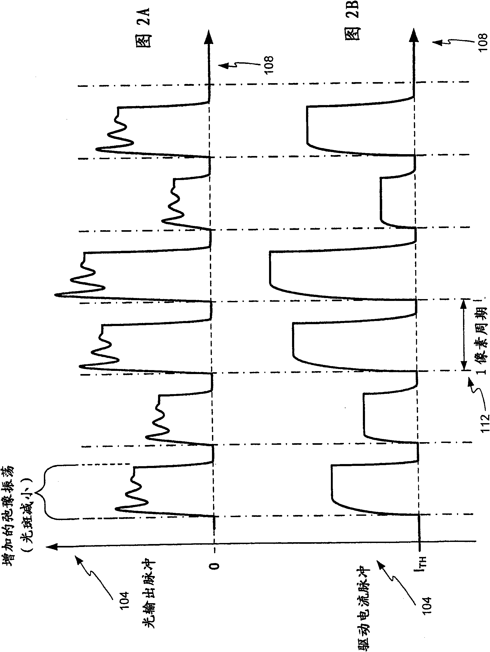
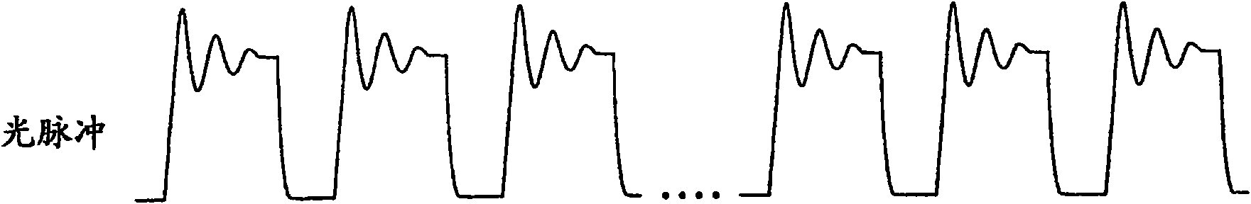
Method and apparatus for reducing optical signal speckle
A technology of optical signals and light spots, applied in optics, optical components, lasers, etc., can solve problems such as increased complexity, cost, size and energy consumption, small effect, lack of solutions, etc.
- Summary
- Abstract
- Description
- Claims
- Application Information
AI Technical Summary
Problems solved by technology
Method used
Image


Examples
Embodiment Construction
[0043] The term optical signal generator as used herein is defined as virtually any device, element or structure that emits light. These may include, but are not limited to, lasers, light emitting diodes, liquid crystal displays, laser diodes, gas lasers, color center lasers, solid state lasers, or any other light source that suffers from speckle or other image degradation due to light interference. The term light as used herein may include any type of light or wavelength of light including, but not limited to, near infrared, far infrared, visible spectrum, or ultraviolet light. The term interference refers to the breadth of the luminescence spectrum of the light energy under consideration. Width is usually measured by the range of wavelengths over which the emitted power falls below half the peak power. For projector applications, emission widths of 1 nm or less are considered "interference". Different applications may consider different spectral widths to be interference. ...
PUM
 Abstract
Description
Claims
Application Information
 - R&D Engineer
- R&D Manager
- IP Professional
- Industry Leading Data Capabilities
- Powerful AI technology
- Patent DNA Extraction
Browse by: Latest US Patents, China's latest patents, Technical Efficacy Thesaurus, Application Domain, Technology Topic, Popular Technical Reports.
© 2024 PatSnap. All rights reserved.Legal|Privacy policy|Modern Slavery Act Transparency Statement|Sitemap|About US| Contact US: help@patsnap.com