
Fuel supply module

A fuel supply and fuel technology, applied in liquid fuel feeders, charging systems, machines/engines, etc., can solve problems such as difficulty in cost reduction, increase in production costs, and impact on the cost of fuel supply modules, so as to reduce production costs , Reduce production cost, simple shape effect

Active Publication Date: 2013-01-09
HONDA MOTOR CO LTD
View PDF1 Cites 0 Cited by
  • Summary
  • Abstract
  • Description
  • Claims
  • Application Information

AI Technical Summary

Problems solved by technology

Therefore, the total production cost of various molding dies increases, which affects the cost of the fuel supply module, so it is extremely difficult to reduce the cost

Method used


Image

  • Fuel supply module
  • Fuel supply module
  • Fuel supply module

Examples


no. 1 example

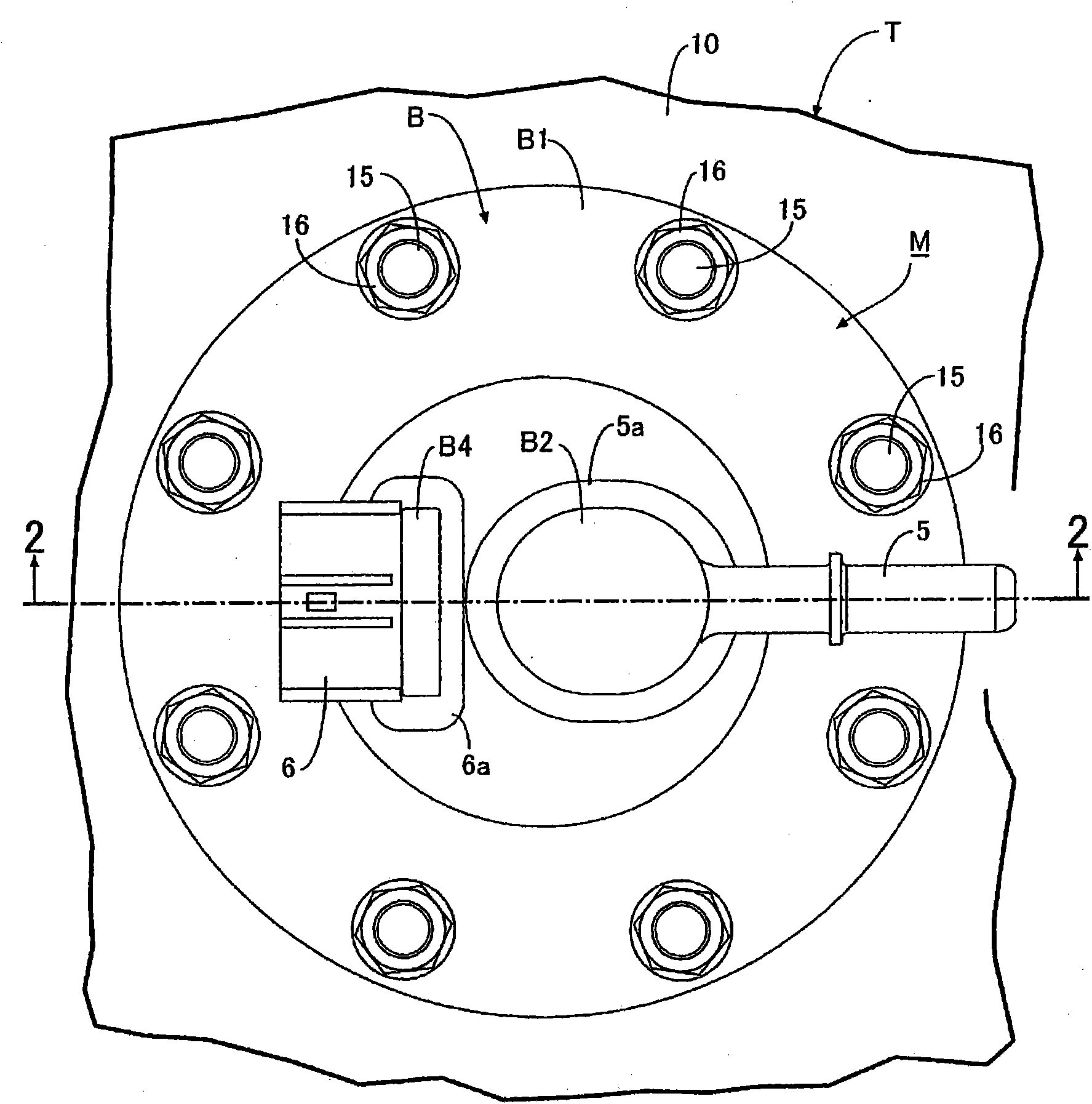
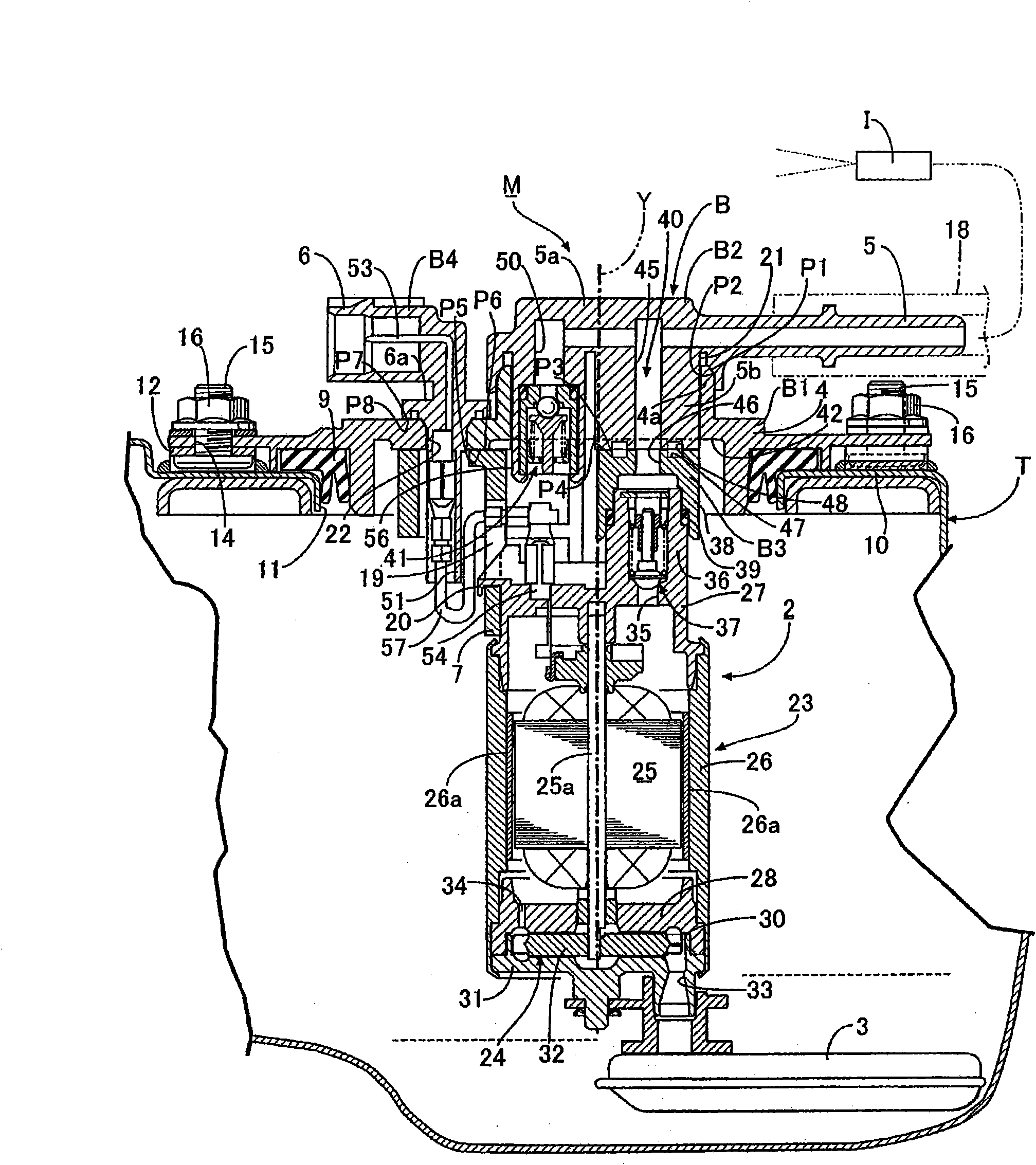
[0023] First, in figure 1 and figure 2 Among them, the fuel supply module M of the present invention that supplies the fuel in the fuel tank T to the fuel injection valve I of the engine is attached to the ceiling wall 10 of the fuel tank T mounted on a vehicle such as a motorcycle.

[0024] The fuel supply module M includes a module body B made of synthetic resin, an electric pump 2 held at the lower portion of the module body B, and a fuel filter 3 attached to the lower end of the electric pump 2 . And, the module main body B is continuously arranged on the installation base 4 by the installation base 4, the fuel delivery pipe 5 protruding from the upper surface of the installation base 4, the coupling 6 protruding from the upper surface of the installation base 4, and the installation base 4. The lower pump holding part 7 constitutes.

[0025] On the other hand, an opening 11 into which the electric pump 2 is inserted is provided inside the top wall 10 of the fuel tank T...


PUM


Abstract

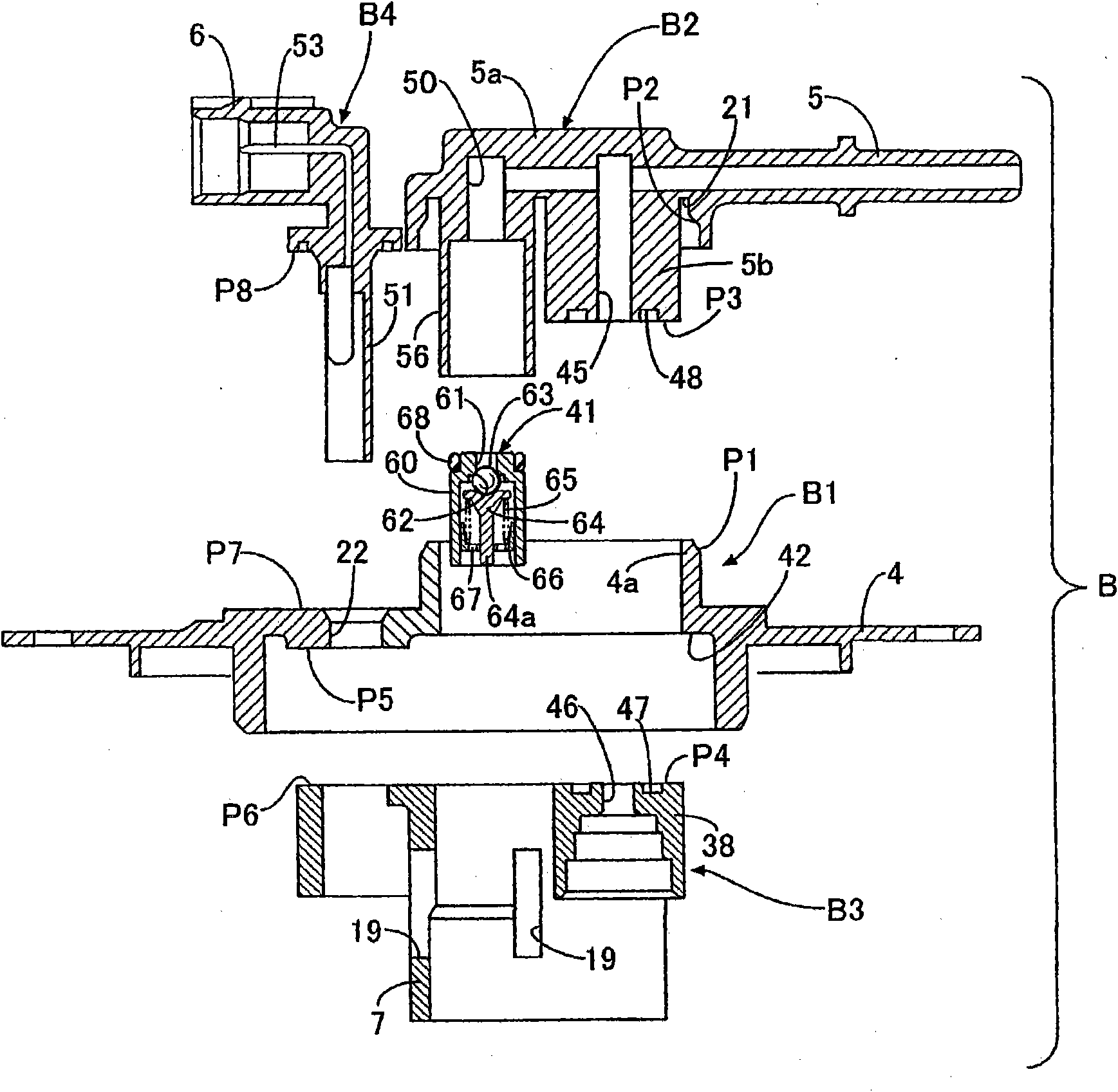
A fuel supply module is provided that includes a module body (B) formed from a mounting base (4), a fuel feed pipe (5), and a pump holding part (7) provided so as to be connected to a lower part of the mounting base (4), wherein the module body (B) is divided into a first block (B1) that includes the mounting base (4), a second block (B2) that includes the fuel feed pipe (5) and its boss (5a), and a fourth block (B4) that includes the pump holding part (7), a boss extension part (5b) extending downward from the boss (5a) is fitted into a support tube (4a) formed in the first block (B1), the support tube (4a) and the second block (B2) are welded, a third block (B3) is welded to an end face of the boss extension part (5b), the first and third blocks (B1, B3) are welded to each other, and the boss extension part (5b) and the third block (B3) are provided with first and second through holes (45, 46). It is thereby possible to provide at low cost a fuel supply module that includes a plurality of types of module bodies having, for example, different directions for a fuel feed pipe.

Description

technical field [0001] The present invention relates to a fuel supply module that mainly supplies fuel to a fuel injection valve of an engine, and particularly relates to an improvement of the fuel supply module as follows. The fuel supply module has a module body composed of the following components: The installation base is installed on the outer wall of the fuel tank; the fuel output pipe protrudes from the upper surface of the installation base; and the pump holding part is continuously provided on the installation base. The lower part of the seat holds the electric pump in the pump holding part, and the electric pump draws fuel in the fuel tank and discharges it to the fuel output pipe through the fuel passage. Background technique [0002] As disclosed in Patent Document 1, such a fuel supply module is known. [0003] Patent Document 1: Japanese Patent Laid-Open No. 2007-291867 [0004] In the conventional fuel supply module of this type, since the module main body i...

Claims


Application Information

Patent Timeline
Patent Type & Authority Patents(China)
IPC IPC(8): F02M37/00F02M37/10
CPCF02M37/103F02M2037/228F02M37/50
Inventor 内藤敏彦林秀树竹中正彦上野正树河野静雄
Owner HONDA MOTOR CO LTD
Learn More