
Heading machine

A technology of roadheader and traveling mechanism, which is applied in the direction of slitting machinery, earthwork drilling and mining, etc., which can solve problems such as rock shedding, and achieve the effect of improving cross-section adaptability

Active Publication Date: 2013-05-22
SANDVIK MINING & CONSTR OY
View PDF3 Cites 0 Cited by
  • Summary
  • Abstract
  • Description
  • Claims
  • Application Information

AI Technical Summary

Problems solved by technology

By means of this program mode, it is particularly tiresome when using the cutting triangles that are retained by the boring machines known in the prior art, and the section rounding (Profilrundungen) on the section edge, because the rock can easily from such remaining cross-sectional areas, they either have to be removed by separating means or pose a considerable risk

Method used


Image

  • Heading machine
  • Heading machine
  • Heading machine

Examples


Embodiment Construction

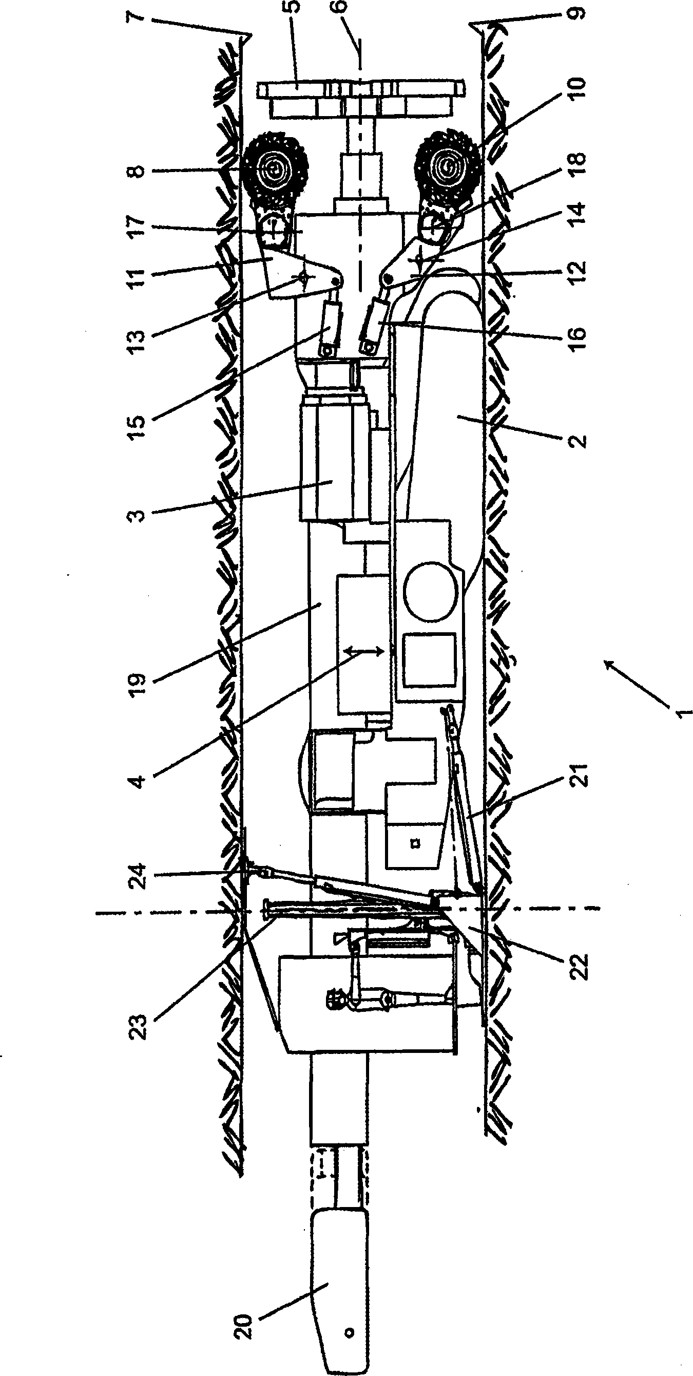
[0017] exist figure 1 In , the roadheader is marked by 1 and has a traveling mechanism 2. The carriage is here configured as a carriage mechanism. A cutting body 5 is mounted on the cutting arm 3 , which can be adjusted vertically along the double arrow 4 by means of a corresponding adjusting device, the cutting body 5 being driven rotatably about an axis of rotation 6 .

[0018] Behind the cutting body 5 there are provided a cutting roller 8 which can be positioned on the top plate 7 and a cutting roller 10 which can be positioned on the bottom plate 9 . Here the cutting rollers 8 and 10 are fixed to a pivot arm 11 or 12 which is pivotable relative to the cutting arm 3 about an axis 13 or 14 . The hydraulic cylinders 15 and 16 each function as a pivot drive. Each of the two cutting rollers 8 and 10 is coupled to a single drive 17 or 18 respectively.

[0019] figure 1 Also depicted is a traction device 19 which extends in the longitudinal direction of the machine as far b...


PUM


Abstract

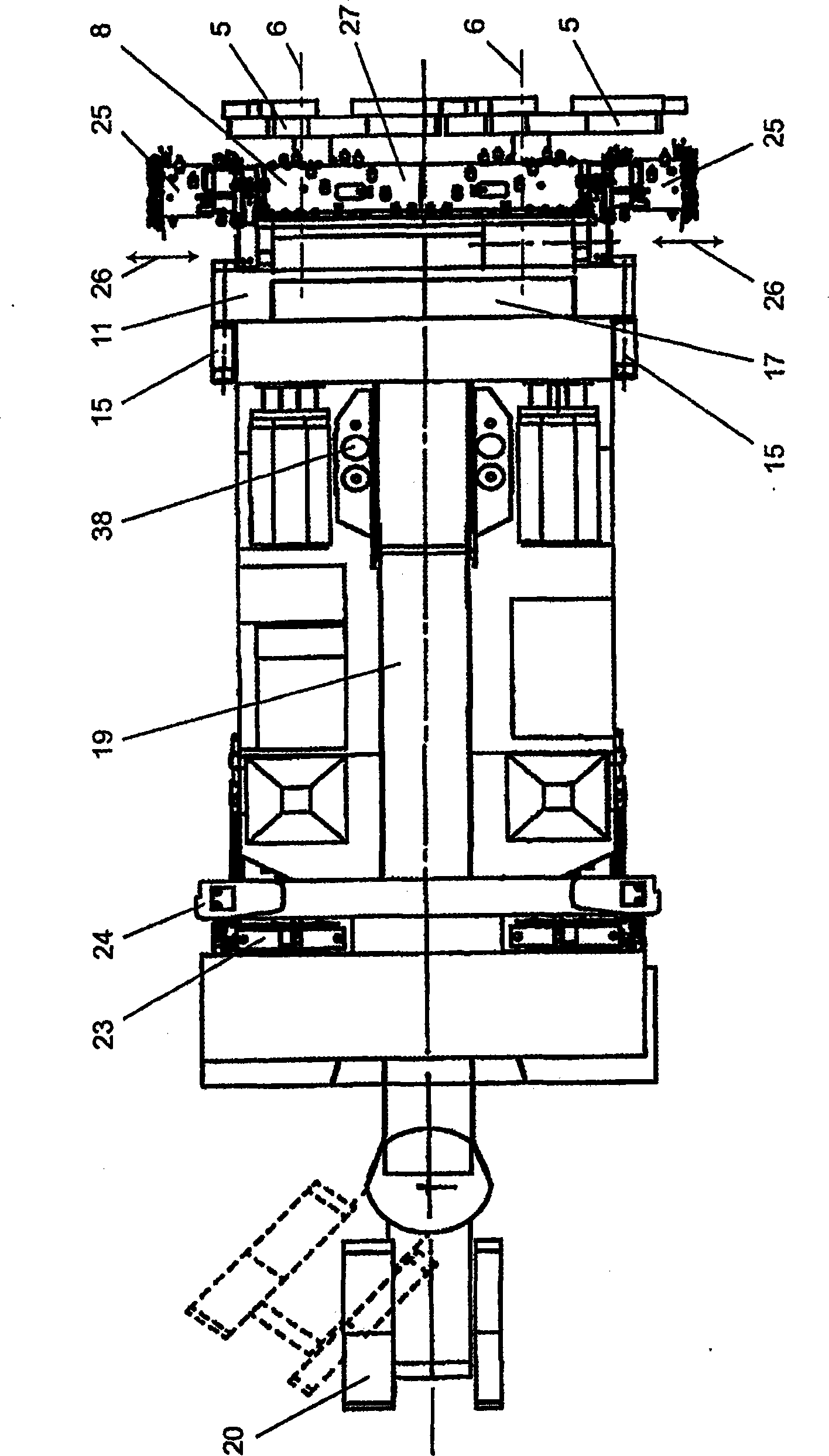
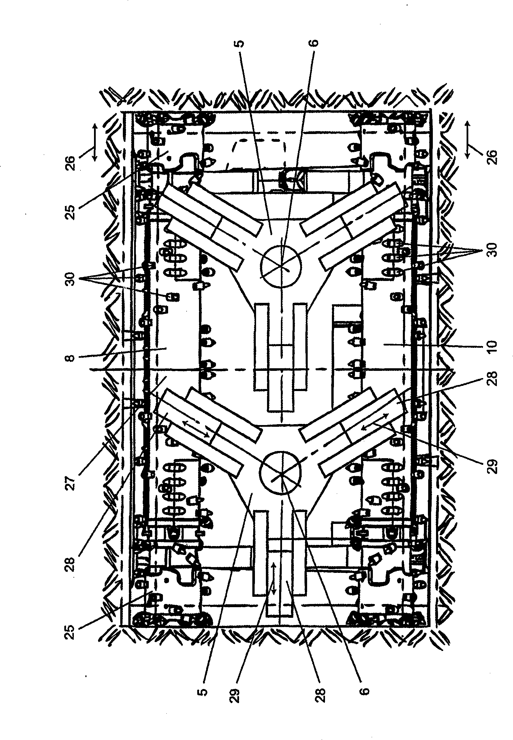
In a heading machine (1) including a travelling mechanism (2) and a cutting boom (3) or frame, the cutting boom (3) or frame carries at least two rotating cutting heads (5) whose axes of rotation (6) extend in the heading direction or enclose acute angles with the heading direction and which, together, define a cutting profile having a profile width (a), as well as two cutting rollers (8,10) arranged substantially parallel and behind the cutting heads (5) and capable of being positioned on the floor (9) and on the roof (7), respectively. Both cutting rollers (8,10) comprise end portions (25) which are extendible to the width (a) of the profile for the formation of a substantially rectangular cutting profile.

Description

technical field [0001] The invention relates to a boring machine (Vortriebsmaschine) with a traveling mechanism (Fahrwerk) and a cutting arm (Schneidausleger) or frame, wherein the cutting arm or frame supports at least two rotating cutting heads and two cutting rollers, at least The axes of rotation of the two rotary cutting heads extend in the direction of penetration or at an acute angle (spitzen Winkel) to the direction of penetration, and the at least two rotary cutting heads together define a cutting section with a profile width, two The cutting rollers are arranged approximately parallel and behind the cutting head and can be positioned on the bottom plate (Sohle) or on the top plate (Firste). Background technique [0002] Road boring machines with a cutting motor whose axis of rotation extends in or at an acute angle to the direction of driving are generally denoted "Marietta Bohrers", wherein the cutting unit comprises two or more rotating cutting heads. The two cu...

Claims


Application Information

Patent Timeline
Patent Type & Authority Patents(China)
IPC IPC(8): E21C27/22
CPCE21C27/22
Inventor B·埃布纳P·科格勒
Owner SANDVIK MINING & CONSTR OY
Learn More