
Finned tube type heat exchanger and manufacture method thereof

A fin-and-tube heat exchanger technology, which is applied to the fin-tube heat exchanger and its manufacturing field, can solve the problem of different heat transfer performance and pressure loss, inability to give full play to the performance of the heat exchanger, and the heat exchange of the heat exchanger. Uneven capacity and other problems, to achieve the effect of reducing useless residual materials, reducing noise, and promoting the flow of condensate water

Active Publication Date: 2012-07-18
MIDEA GRP CO LTD
View PDF3 Cites 0 Cited by
  • Summary
  • Abstract
  • Description
  • Claims
  • Application Information

AI Technical Summary

Problems solved by technology

Although this alleviates the problem caused by the folding angle, due to the angle and width changes at the joints of the curved fins, it will still disturb the flow to a certain extent, and the condensed water may also drip or drop at the curved fins. drawn into the cross-flow fan
In addition, neither of these two solutions can solve the problem of increased noise caused by the downwind edge of the fin being too close to the cross-flow fan due to the use of parallel straight-line fins on the lower side of the second heat exchanger
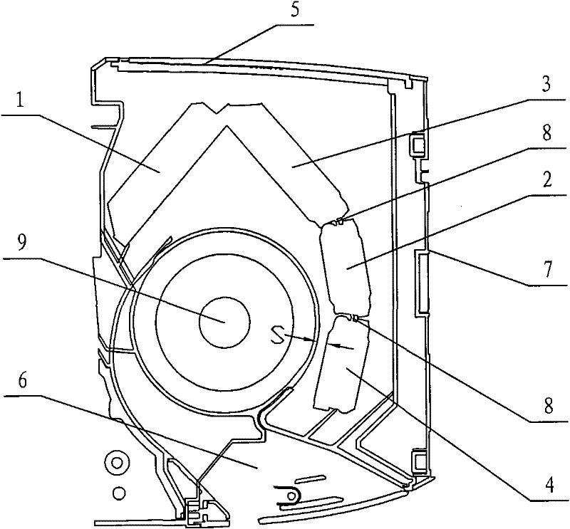
[0006] In addition, since the air inlet 5 of the indoor unit of the air conditioner is located on the top of the indoor unit, and the air outlet 6 is located on the lower side of the indoor unit, it is located on the upper side of the first heat exchanger 1 and the second heat exchanger 2 near the air inlet 5. The air volume is larger and the wind speed is faster, the air volume on the lower side of the second heat exchanger 2 is smaller, the wind speed is slower, and the performance of the heat exchanger here cannot be fully utilized. In order to give full play to the lower part of the second heat exchanger 2 performance, it is necessary to make the wind speed distribution on the heat exchanger as uniform as possible, and to increase the wind speed of the lower part of the second heat exchanger 2
[0007] The heat transfer tubes of the multi-fold heat exchanger of the indoor unit of the air conditioner are generally designed with the same diameter, but the refrigerant flowing in the tube of the indoor unit of the air conditioner may be in the gaseous state, the liquid state, and the two-phase region where the two phases of gas and liquid coexist. The heat transfer performance and pressure loss in these different areas are different, which will lead to uneven heat transfer capacity of the heat exchanger and reduce the overall heat transfer capacity

Method used


Image

  • Finned tube type heat exchanger and manufacture method thereof
  • Finned tube type heat exchanger and manufacture method thereof
  • Finned tube type heat exchanger and manufacture method thereof

Examples


Embodiment Construction

[0043] The present invention will be further described below in conjunction with the accompanying drawings and embodiments.

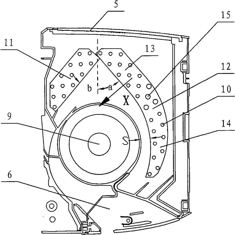
[0044] see Figure 3-Figure 4 , the second heat exchanger fin 12 of this finned tube heat exchanger is a curved whole, formed by folding the second heat exchanger fin 12 and the first heat exchanger fin 11 as image 3 In the shown heat exchanger, the first heat exchanger fin 11 and the second heat exchanger fin 12 are folded into an inverted V shape above the cross-flow fan 9, and the second heat exchanger fin 12 is approximately C-shaped. ; Then, assemble the heat exchanger in the frame of the indoor heat exchanger to form as figure 2 Air conditioner indoor unit shown.

[0045] The upper fins 13 of the second heat exchanger fins and the edges of the first heat exchanger fins 11 are parallel straight lines. The edge of the lower fin 14 in the second heat exchanger fin is arc-shaped. In the average airflow direction, that is, along the X direction i...


PUM


Abstract

The invention relates to a finned tube type heat exchanger and a manufacture method thereof. The finned tube type heat exchanger is arranged in an indoor unit frame with an air inlet and an air outlet. A flow-through fan is also arranged in the indoor unit frame, and the finned tube type heat exchanger is arranged around the flow-through fan. The finned tube type heat exchanger comprises a first heat exchanger fin and a second heat exchanger fin. The second heat exchanger fin comprises an upper fin and a middle and lower fin; and the edge of the middle and lower fin is an arc. The average airflow direction flowing through the whole second exchanger fin is set as an X direction. The distances between the air-feeding edges and the air-exhausting edges at all positions of the second exchanger fin along the average airflow direction are same, wherein the air-exhausting edge of the middle and lower fin is tangent to the air-exhausting edge of the upper fin at a first tangency point; and the air-feeding edge of the middle and lower fin is tangent to the air-feeding edge of the upper fin at a second tangency point. The invention has the characteristics of increasing the heat exchanging capacity, enlarging the air quantity, reducing the noise, and promoting the exhaustion of condensate water.

Description

technical field [0001] The invention relates to a finned tube heat exchanger and a manufacturing method thereof. Background technique [0002] see figure 1 , the multi-fold heat exchanger of the traditional air-conditioning indoor unit improves the utilization efficiency of the cross-flow fan 9 and reduces the size of the air-conditioning indoor unit by surrounding the cross-flow fan 9 . When making the multi-fold heat exchanger, fins with parallel straight edges are used. First, the fins with parallel straight edges are cut off at part 2, and then folded around the cross-flow fan 9. However, if figure 2 As shown, when producing such fins whose edges are parallel and straight lines by stamping, part of the fins located at the first corner 22 needs to be cut off at the fold, which will waste material. A certain extra space is required when folding, which will increase the width and size of the air conditioner indoor unit. Moreover, the folded part 8 will disturb the air ...

Claims


Application Information

Patent Timeline
Patent Type & Authority Patents(China)
IPC IPC(8): F25B39/00F24F13/30F24F13/24B21D53/08
Inventor 岳宝张智伍光辉
Owner MIDEA GRP CO LTD
Learn More