
Trench-type Schottky-barrier diode rectifier and preparation method

A technology of diode rectification and Schottky potential, which is applied in semiconductor/solid-state device manufacturing, electric solid-state devices, semiconductor devices, etc., and can solve the problem of increased reverse leakage, poor gap filling ability, and decreased reverse blocking ability, etc. problem, to achieve the effect of high voltage reverse blocking ability, overcoming tip discharge effect, and strong gap filling ability

Active Publication Date: 2010-12-01
SUZHOU SILIKRON SEMICON CO LTD
View PDF4 Cites 5 Cited by
  • Summary
  • Abstract
  • Description
  • Claims
  • Application Information

AI Technical Summary

Problems solved by technology

However, the exposed weaknesses of this structural design are: 1. Since the apex 9 of the boss directly contacts the upper metal layer 6, there is a tip discharge effect (the small radius of curvature causes the electric field intensity to increase), which easily causes reverse leakage. 2. During the manufacturing process, because the silicon dioxide layer 5 on the side of the apex 9 of the boss is easily damaged locally, the side of the apex 9 of the boss is directly in contact with the upper metal layer 6, resulting in The reverse leakage becomes larger, and the reverse blocking ability decreases; 3. The metal filled in the trench 3 is the same as the upper metal layer 6. When the width of the trench 3 is narrow, the gap filling ability of the material of the upper metal layer 6 is not good. May leave voids and affect device reliability

Method used


Image

  • Trench-type Schottky-barrier diode rectifier and preparation method
  • Trench-type Schottky-barrier diode rectifier and preparation method
  • Trench-type Schottky-barrier diode rectifier and preparation method

Examples


Embodiment 1

[0036] Embodiment 1: A trench type Schottky barrier diode rectifier device and its manufacturing method

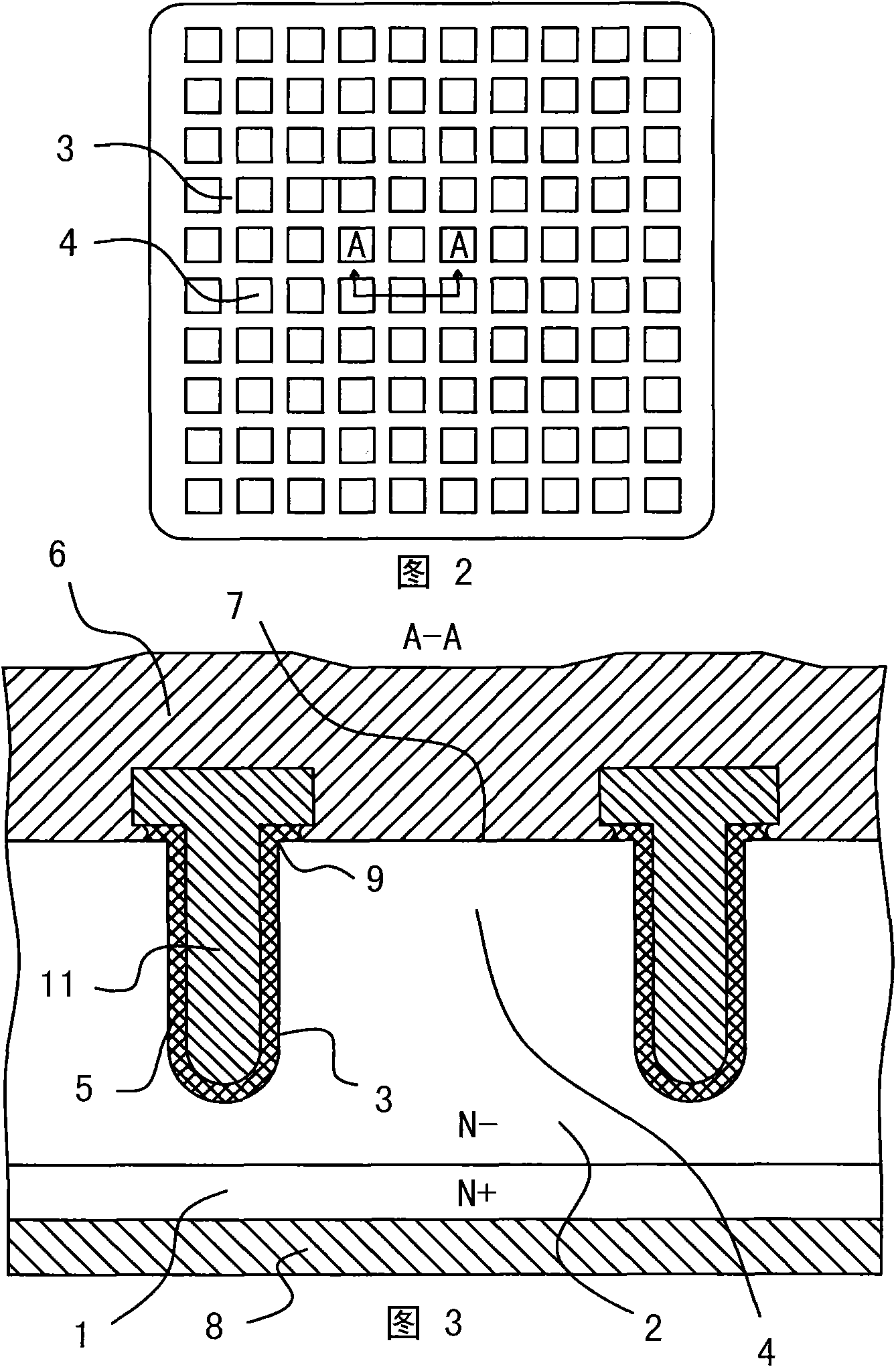
[0037] like figure 2 and image 3 Shown, the trench type Schottky barrier diode rectifier device structure of the present invention is: on the top view plane (see figure 2 ), the active region of the device consists of several Schottky barrier diode cells connected in parallel. On a longitudinal section through the center of the Schottky barrier diode unit cell (see image 3 ), each Schottky barrier diode unit cell is composed of lower metal layer 8, N+ monocrystalline silicon substrate 1, N- epitaxial layer 2 and upper metal layer 6 from bottom to top, wherein in the N- epitaxial On the upper part of the layer 2, grooves 3 are spaced apart laterally, and the N-epitaxial layer 2 region between two adjacent grooves 3 forms an N-monocrystalline silicon boss structure 4, and the top surface of the boss structure 4 is connected to the upper metal layer 6 The contact forms ...

Embodiment 2

[0057] Example 2: A Trench Schottky Barrier Diode Rectifier Device and Manufacturing Method

[0058] like Figure 4 As shown, the difference between this embodiment and Embodiment 1 is that: from the top view plane of the rectifier device, the pattern of the trench 3 is different, the embodiment 1 is grid-like, and the Schottky barrier diode cells are arranged in an array small square. And the figure of present embodiment groove 3 from Figure 4 It can be seen in the figure that they are strips parallel to each other, and the Schottky barrier diode cells are strips parallel to each other. Other contents are the same as those in Embodiment 1, and will not be described again here.

[0059] Through Embodiment 1 and Embodiment 2, it can be seen that the planar layout and shape of the unit cell of the rectifier device can have other changes, such as the shape of the unit cell is prismatic, circular, triangular, etc., and the layout can be from the inside to the outside. size ri...


PUM


Abstract

The invention provides a trench-type Schottky-barrier diode rectifier and a preparation method. By using the two shoulders of a conducting poly-silicon T-shaped head in the trench and the silica layers on the extended sections to cover the vertex angles of boss structures on two sides of the trench, the invention, based on the existing trench-type Schottky diode rectifiers, overcomes the problems of increase in inverse current leakage and reduction in inverse blocking capacity caused by the tip discharge effect produced by contact of the vertex angles of the boss and an upper metal layer; moreover, by filling the trench with the conducting poly-silicon instead of aluminum, titanium and other conventional materials of the upper metal layer, on one hand, the invention solves the problem that the reliability of the rectifier is influenced by hollow cavities left during trench filling, and on the other hand, the invention provides more flexible design space for the ratio of the opening width to depth of the trench of the diode rectifier.

Description

technical field [0001] The invention relates to a rectifying device and a manufacturing method thereof, in particular to a trench type metal-semiconductor Schottky barrier diode rectifying device and a manufacturing method thereof. Background technique [0002] As a conversion device from AC to DC, rectifier devices require unidirectional conduction characteristics, that is, low turn-on voltage and small on-resistance during forward conduction, and high blocking voltage and small reverse leakage when reversed. [0003] Schottky diodes have been used in power supply applications for decades as rectification devices. Compared with PN junction diodes, Schottky diodes have the advantages of low forward turn-on voltage and fast switching speed, which makes them very suitable for switching power supplies and high-frequency applications. The reverse recovery time of the Schottky diode is very short, which is mainly determined by the parasitic capacitance of the device, not by the ...

Claims


Application Information

Patent Timeline
IPC IPC(8): H01L27/08H01L29/872H01L29/06H01L21/329H01L21/762
Inventor 刘伟王凡程义川
Owner SUZHOU SILIKRON SEMICON CO LTD
Learn More