Equipment and method for manufacturing liquid crystal optical element

A technology of liquid crystal optics and manufacturing equipment, applied in optics, nonlinear optics, instruments, etc., can solve problems such as restricting industrial upgrading, unfavorable development of liquid crystal optical components, and difficulty in achieving alignment effect by rubbing method, and achieves elimination of dust and static electricity. The effect of improving yield and quality

Active Publication Date: 2010-11-24
SUPERD CO LTD
View PDF5 Cites 6 Cited by
  • Summary
  • Abstract
  • Description
  • Claims
  • Application Information

AI Technical Summary

Problems solved by technology

In addition, the friction method is also limited to alignment on a plane. For curved substrates, it is difficult to achieve a consistent alignment effect with the friction method.
These are the disadvantages of the friction method, which is not conducive to the further development of the manufacture of liquid crystal optical components and restricts the upgrading of the industry

Method used


Image

  • Equipment and method for manufacturing liquid crystal optical element
  • Equipment and method for manufacturing liquid crystal optical element
  • Equipment and method for manufacturing liquid crystal optical element

Examples


Embodiment Construction

[0025] The present invention will be described in detail below in conjunction with the accompanying drawings and embodiments.

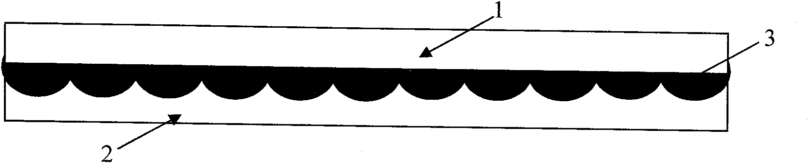
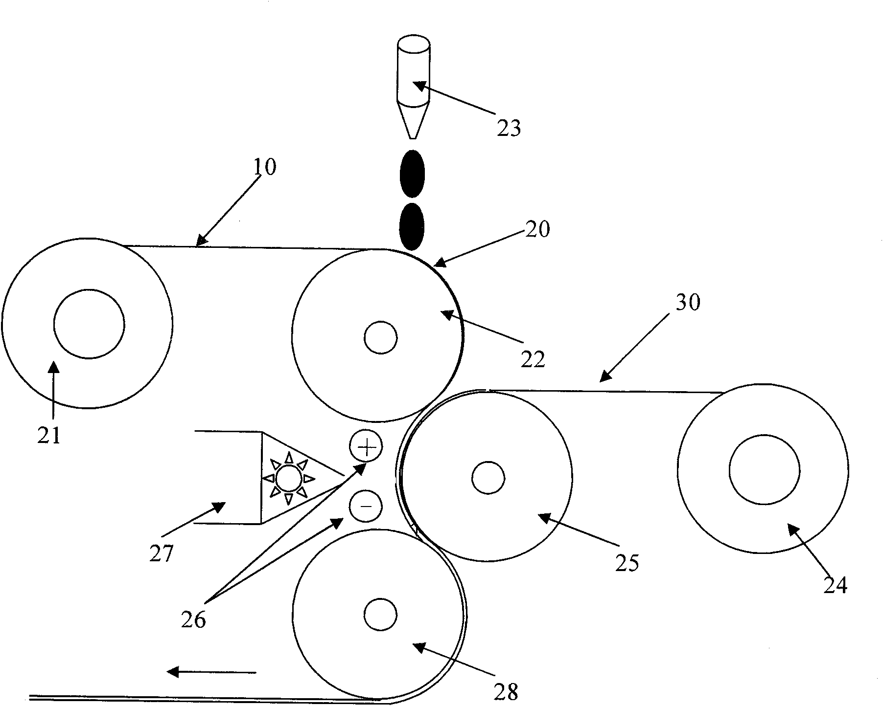
[0026] Such as figure 2 As shown, the present invention provides a manufacturing equipment of a liquid crystal optical element. This manufacturing facility can be used to manufacture figure 1 The liquid crystal birefringent grating is shown. The manufacturing equipment mainly includes a first delivery roller 21, a first transfer roller 22, a liquid crystal distribution device 23, a second delivery roller 24, a second delivery roller 25, an electric field generating device 26, a curing device 27 and a first Three transfer rollers 28 .

[0027] In operation, the substrate 10 placed in the first sending roller 21 is conveyed by the first conveying roller 22 . In this embodiment, the substrate 10 is a PET substrate, and is placed in the first delivery roller 21 in rolls. The liquid crystal dispensing device 23 dispenses the liquid crystal material 2...


PUM


Abstract

The invention provides equipment and a method for manufacturing a liquid crystal optical element. The manufacturing equipment comprises a first transmitting device used for transmitting a substrate, a liquid crystal distribution device used for distributing liquid-state liquid crystal materials for the surface of the substrate, an electric field generating device used for generating an electric field so as to distribute directions for liquid crystal molecules in the liquid-state liquid crystal materials, and a curing device used for curing the liquid-state liquid crystal materials when the electric field generating device distributes directions for the liquid crystal molecules. Due to the mode, in the process of manufacturing the liquid crystal optical element, by performing non-contact direction distribution on the liquid crystal molecules by using the electric field, dust and static generated due to friction in a friction method can be effectively eliminated, and the finished product ratio and quality of the liquid crystal optical element are improved.

Description

【Technical field】 [0001] The invention relates to an optical element manufacturing equipment and a manufacturing method, in particular to a liquid crystal optical element manufacturing equipment and a manufacturing method. 【Background technique】 [0002] Liquid crystal optical elements are widely used in various display fields. Such as figure 1 as shown, figure 1 A liquid crystal birefringent grating applied in a 2D / 3D point-by-point switching stereoscopic display is shown. The liquid crystal birefringence grating includes a substrate 1 , a sub-mode grating 2 and a liquid crystal layer 3 sandwiched between the substrate 1 and the sub-mode grating 2 . In the above-mentioned liquid crystal birefringent grating and other liquid crystal optical elements, it is often necessary to align the liquid crystal molecules in the liquid crystal layer 3 so that the liquid crystal molecules are arranged in a predetermined direction as required. [0003] The current alignment technology ...

Claims


Application Information

Patent Timeline
IPC IPC(8): G02F1/1333G02F1/1337
Inventor 杨扬罗杰
Owner SUPERD CO LTD
Why Eureka
Try Eureka