
Movable wind power generator

A wind power generation equipment and power technology, which is applied in the direction of wind power generator components, wind power engines, wind power motor combinations, etc., can solve the problems affecting the application range and economic effect of wind power generators, the inability to receive wind power in all directions, and the low utilization efficiency of wind energy, etc. , to achieve the effect of simple structure, compact size and small footprint

Inactive Publication Date: 2010-11-17
钟明华
View PDF6 Cites 2 Cited by
  • Summary
  • Abstract
  • Description
  • Claims
  • Application Information

AI Technical Summary

Problems solved by technology

[0003] At present, the known wind generators generally include wheeled wind generators, vertical wind generators, tower wind generators, propeller generators... No matter what structure these wind generators adopt, they need to dig the foundation, Laying foundations and erecting a set of towering and large-looking institutions takes up a lot of space, and there are defects such as low wind energy utilization efficiency, inability to move and use, and inability to receive wind force in all directions, which affects the application range and economic effect of wind turbines.

Method used


Image

  • Movable wind power generator
  • Movable wind power generator
  • Movable wind power generator

Examples


Embodiment Construction

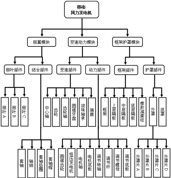
[0033] As a product technical solution, the present invention can be implemented through the combination of specific modules. The organizational structure between each module and parts of the product of the present invention, such as figure 1 shown.

[0034] figure 1 Among them, the mobile wind power generator described in the present invention is composed of three modules: fan blade, variable speed power, and frame shield, and each module contains different components, wherein:

[0035] ◆Fan wing module──contains the fan blade and combines two parts.

[0036] ◆Variable speed power module──Contains two components of speed change and power.

[0037] ◆Frame shield module──contains frame and shield.

[0038] Each component of the product contains several different parts; some of the parts contain several components, among which:

[0039] ◇Blade parts──Contains three parts: blade A, blade B, and blade C.

[0040] ◇Combined parts──Contains four parts: sleeve shaft, shaft pi...


PUM


Abstract

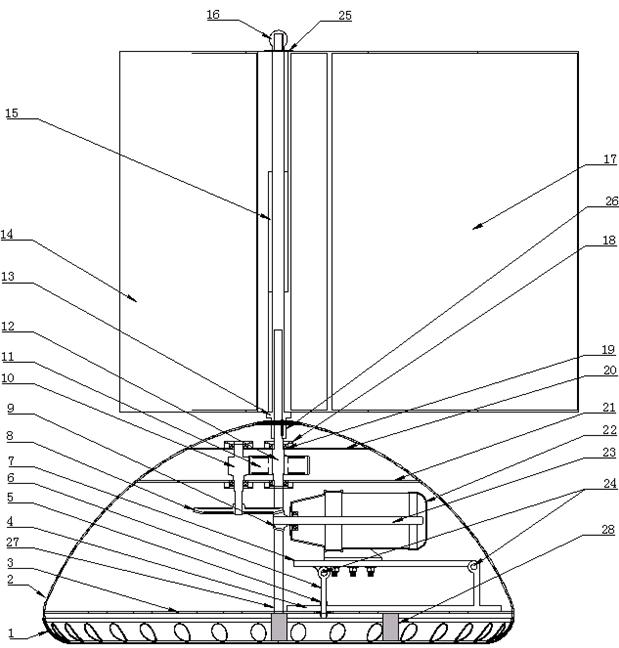
The invention relates to a wind power generator, in particular to a movable wind power generation device adopting a three-ridge fan wing structure. The movable wind power generation device consists of a fan wing module, a variable speed power module and a framework shielding module, and comprises 28 components of a bottom cover, an outer cover, a bottom layer clapboard, an adjusting base plate, an adjusting nut, an adjusting lever, a motor base plate, a bevel gear, conical chain wheel, a gear shaft, a gear, a center shaft, a sleeve shaft, a fan blade C, a fan blade B, a sleeve shaft cap, a fan blade A, an end cap, a ball bearing, an upper layer clapboard, a middle layer clapboard, a constant voltage generator, a motor shaft, an adjustable rotating shaft, a sleeve shaft washer, a shaft pin, a framework and a rubber shock absorber strut. The movable wind power generator overcomes the defects that the current well known wind power generator has a huge volume, a low wind energy utilization ratio, immovability and the like, forms the wind power generation device with a lean volume, reliable operation, strong adaptability and wide application range, is particularly suitable for the requirements of non-fixed occasion industries such as ocean fishery, ocean navigation, field operation, emergency rescue and disaster relief and the like in addition to usages in fixed occasions such as families, factories, livestock farms, farms, forest farms, playgrounds and the like, and has a wide market space, extremely high economic added value and social use value.

Description

technical field [0001] The invention relates to a wind power generator, in particular to a movable wind power generating device adopting a triangular fan wing structure. Background technique [0002] A wind turbine, also known as a "windmill", is a device that uses natural wind as energy to obtain a certain amount of power; the device that uses natural wind to obtain electrical energy is a wind generator. [0003] At present, the known wind generators are common wheeled wind generators, vertical wind generators, tower wind generators, propeller generators... No matter what structure these wind generators adopt, they need to dig the foundation. Laying foundations, erecting a set of towering and large-looking institutions, takes up a lot of space, and has defects such as low wind energy utilization efficiency, inability to move and use, and inability to receive wind force in all directions, which affects the application range and economic effect of wind turbines. . purpose...

Claims


Application Information

Patent Timeline
IPC IPC(8): F03D9/00F03D3/06F03D7/06F03D11/00F03D9/25F03D15/10F03D80/00
CPCY02E10/74Y02B10/30Y02P80/20
Inventor 钟明华
Owner 钟明华
Learn More