Oil-gas separator

A technology of oil-gas separator and air outlet pipe, which is applied in the direction of refrigeration components, refrigerators, lighting and heating equipment, etc. It can solve the problems of low assembly efficiency, troublesome manufacturing, troublesome assembly, etc., achieve high assembly efficiency, reduce overall cost, Produce simple effects

Inactive Publication Date: 2010-11-10
NINGBO AUX ELECTRIC
View PDF5 Cites 3 Cited by
  • Summary
  • Abstract
  • Description
  • Claims
  • Application Information

AI Technical Summary

Problems solved by technology

[0003] Since the filter screen is made of thicker steel wire mesh, it is difficult to punch holes and inconvenient to process. In addition, when assembling the above-mentioned oil-gas separator, the air outlet pipe and the air inlet pipe must first be passed through the through holes on the filter screen, so that the air outlet pipe, The air inlet pipe and the filter screen are connected first, then the filter screen is installed in the cylinder body, and then the upper cover is connected with the cylinder body, so that only part of the air outlet pipe and the air inlet pipe are exposed outside, that is, the air outlet of the air out...

Method used


Image

  • Oil-gas separator
  • Oil-gas separator
  • Oil-gas separator

Examples


Embodiment Construction

[0017] The present invention will be further described below in conjunction with accompanying drawing.

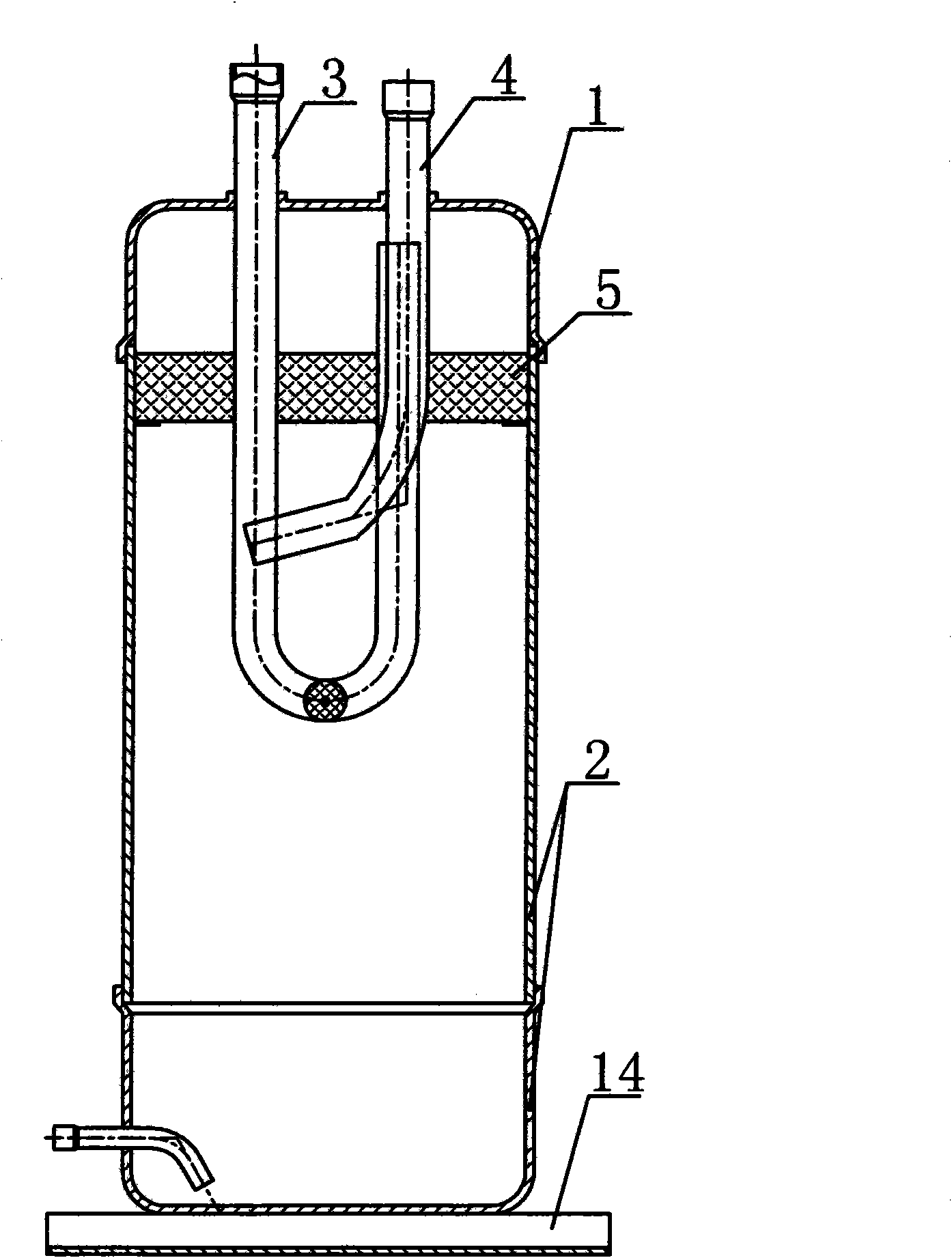
[0018] like figure 1 Or 2 is a schematic structural diagram of an oil-gas separator in the prior art, and its structure has been introduced in detail in the background technology section, so it will not be repeated here.

[0019] The oil-gas separator of the present invention is composed of an upper cover 1, a cylinder body 2, an air outlet pipe 3, an air inlet pipe 4, a filter screen 5 and an oil return pipe, the upper cover 1 is connected with the cylinder body 2 to form a cavity, and the upper cover 1 is marked with Two through holes for air outlet pipe 3 and air inlet pipe 4 to pass through, and at the passing position, air outlet pipe 3 and air inlet pipe 4 are respectively connected to upper cover 1, and the filter screen 5 is provided with a hollow part 10, and the air outlet pipe 4 is connected to the upper cover 1 respectively. The air pipe 3 communicates with the...


PUM


Abstract

The invention discloses an oil-gas separator which has simple manufacturing and high assembling efficiency and therefore reduces in comprehensive cost. The oil-gas separator consists of an upper cover (1), a cylinder (2), a gas outlet pipe (3), a gas inlet pipe (4), a filter screen (5) and an oil return pipe, wherein the upper cover (1) is connected with the cylinder (2) to form a cavity; two through holes through which the gas outlet pipe (3) and the gas inlet pipe (4) pass are formed on the upper cover (1); the gas outlet pipe (3) and the gas inlet pipe (4) are connected with the upper cover (1) respectively at the through part; the filter screen (5) is provided with a hollow part (10); the gas outlet pipe (3) is communicated with the hollow part (10) and the filter screen (5) is connected with the upper cover (1).

Description

technical field [0001] The invention relates to the technical field of oil-gas separation equipment used in refrigeration systems, in particular to an oil-gas separator. Background technique [0002] At present, there is an oil-gas separator, which is composed of an upper cover, a cylinder body, an air outlet pipe, an air inlet pipe, a filter screen and an oil return pipe. The filter screen is installed in the cylinder body horizontally, thereby separating the cavity formed by connecting the upper cover and the cylinder body The cylinder is installed on the base, and there are three through holes on the filter, two of which are used for the outlet pipe to pass through. The purpose is to make the curved section of the outlet pipe located in the lower cavity, and the air inlet of the outlet pipe It is located in the upper cavity, and the remaining through holes are used for the passage of the air intake pipe, so that the air outlet of the air intake pipe is located in the lowe...

Claims


Application Information

Patent Timeline
IPC IPC(8): F25B43/02
Inventor 郑坚江魏爱国
Owner NINGBO AUX ELECTRIC
Why Eureka
Try Eureka