
Deformable wheel device

A technology of deformed wheels and rims, applied in the directions of wheels, transportation and packaging, vehicle parts, etc., can solve the problems of complex structure, high cost and difficult maintenance of deformed wheels.

Inactive Publication Date: 2010-11-03
CHINA NORTH VEHICLE RES INST
View PDF3 Cites 10 Cited by
  • Summary
  • Abstract
  • Description
  • Claims
  • Application Information

AI Technical Summary

Problems solved by technology

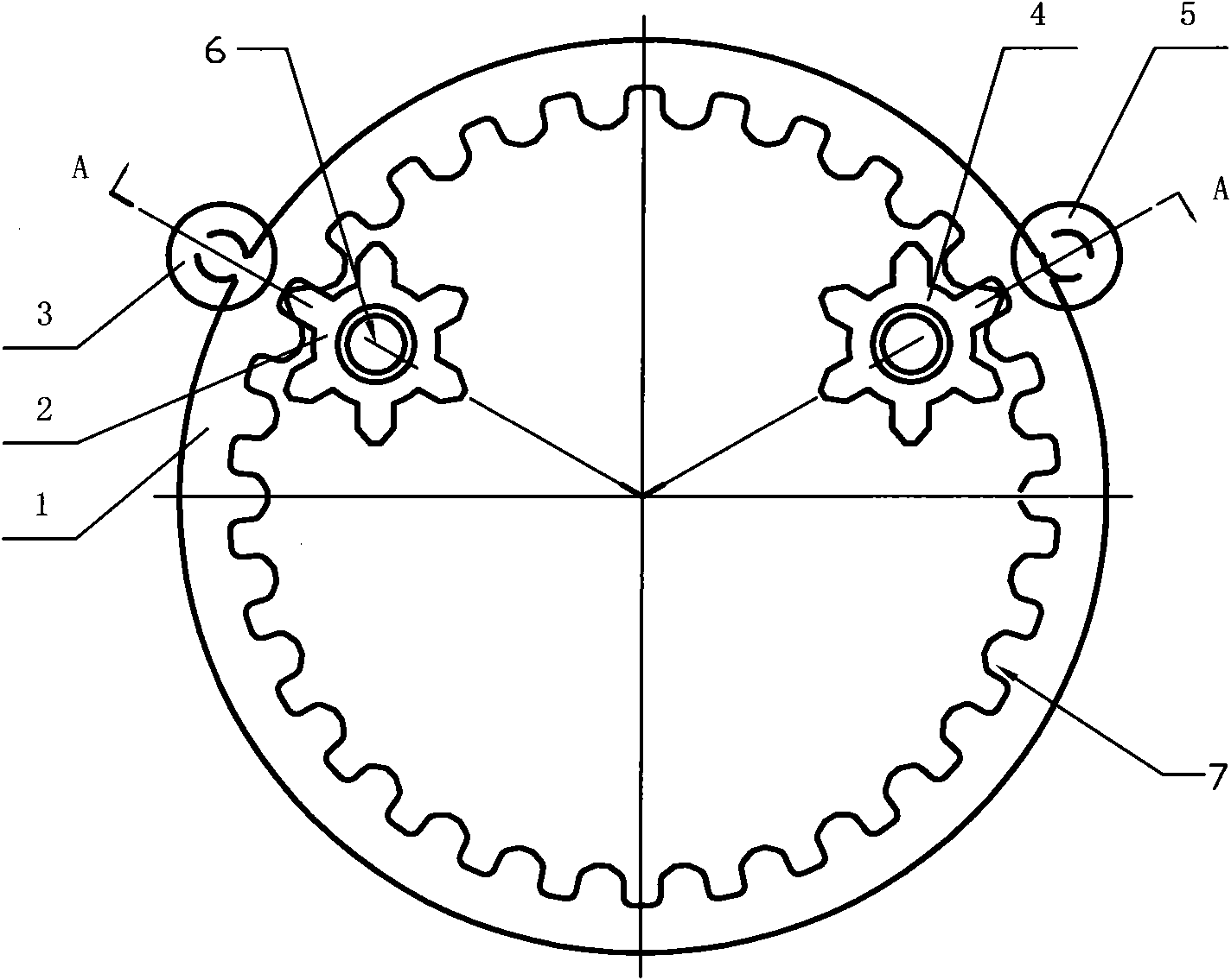
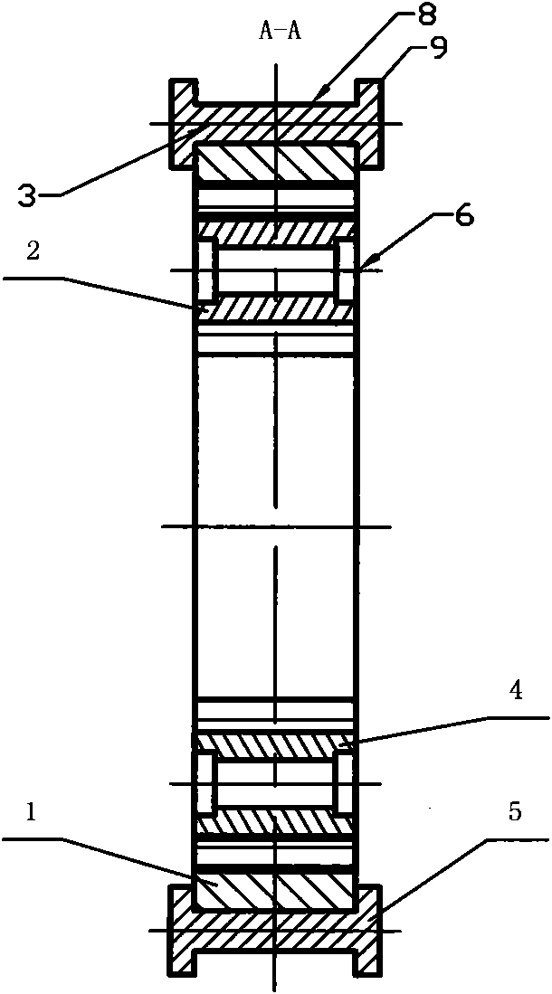
[0007] In order to solve the problems of complex structure, high cost, difficult maintenance and small application range of deformable wheels in the prior art, the present invention provides a deformable wheel with simple structure, convenient adjustment and suitable for hard and soft roads. The specific scheme is as follows: A deformed wheel device, including a deformed rim and a drive shaft, characterized in that the deformed rim is made of elastic material, and the inner surface of the deformed rim has an internal gear, and the internal gear is engaged with a driving wheel and a guide wheel , the driving wheel and the guide wheel are symmetrically arranged on both sides of the vertical line of the center of the deformed rim, and the limit wheel A and the limit wheel B are respectively installed on the opposite sides of the drive wheel and the guide wheel on the outer surface of the deformed rim, and the limit wheel A and The center of the driving wheel is collinear, the center of the limit wheel B and the guide wheel are collinear, the drive wheel is connected with the drive shaft of the vehicle, and the limit wheel A, limit wheel B and the guide wheel are connected with the vehicle body through the support shaft

Method used


Image

  • Deformable wheel device
  • Deformable wheel device
  • Deformable wheel device

Examples


Embodiment Construction

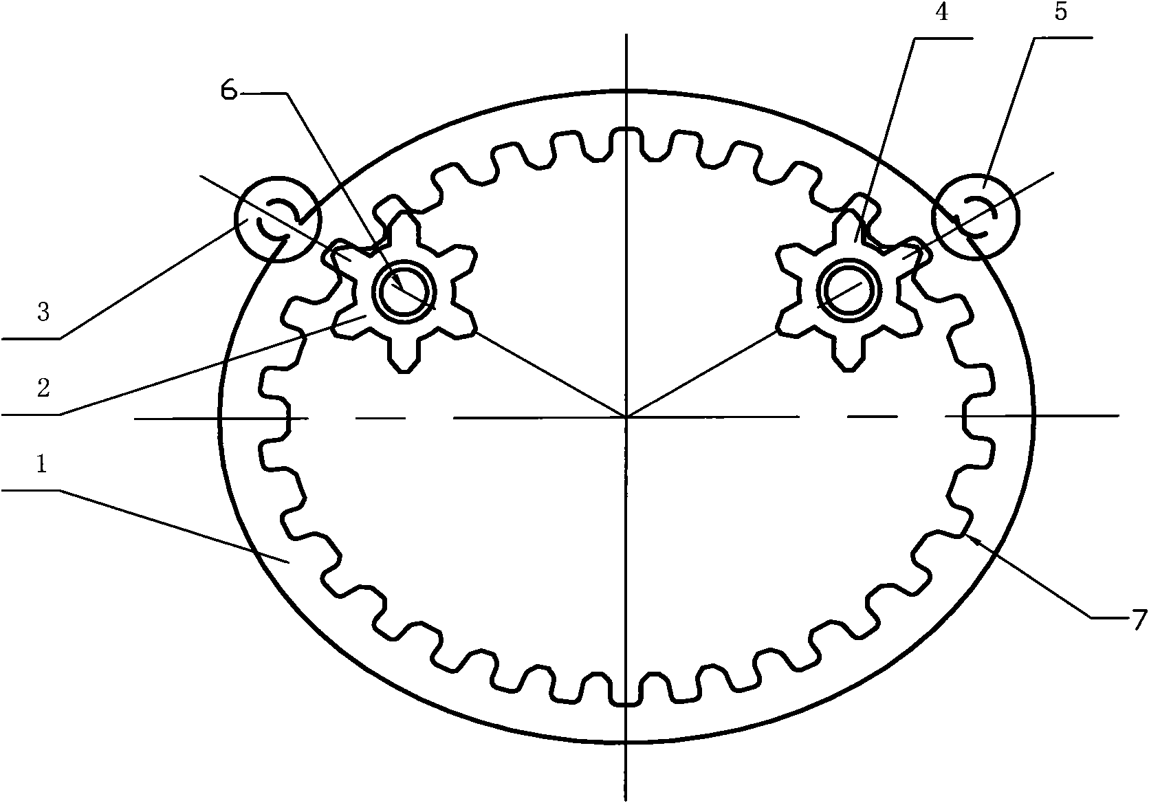
[0021] Such as figure 1 , 2 , 3, the deformation wheel of this program is made up of deformation rim 1, drive wheel 2, spacer wheel A3, guide wheel 4, spacer wheel B5 and adjustment device, deformation rim 1 outer surface is the same as ordinary wheel, There are friction lines, but the inside of the deformation rim is not inflated, but adopts a solid structure. There is an inner ring gear 7 on the inner surface of the deformation rim 1, and the driving wheel 2 and the guide wheel 4 installed on the car body are used to form a solid structure. In the way of meshing, the deformed rim is driven from the inside of the deformed rim 1, and the driving wheel 2 is connected to the drive shaft 6 of the vehicle. In order to ensure the control of the deformed rim, a corresponding limit wheel A3 is installed at the driving wheel and the guide wheel , limit wheel B5, the center of limit wheel A and limit wheel B is the rolling shaft 8, the two ends of the rolling shaft 8 are equipped with...


PUM


Abstract

The invention discloses a deformable wheel device, in particular to a deformable wheel which is used for a light vehicle and can adapt to different pavements. The deformable wheel comprises a deformable rim and a driving shaft, wherein an inner gear ring is arranged on the inner surface of the deformable rim; a driving wheel and a guide wheel are meshed on the inner gear ring; the driving wheel and the guide wheel are symmetrically arranged at two sides of the vertical line of the center of a circle of the deformable rim; a spacing wheel A and a spacing wheel B are respectively installed at the opposite parts of the driving wheel and the guide wheel on the outer surface of the deformable rim; the centers of the spacing wheel A and the driving wheel are positioned on the same line; and thecenters of the spacing wheel B and the guide wheel are positioned on the same line. When a vehicle is loaded, the deformable wheel of the invention deforms into a similar ellipse from a circle, thereby changing the ground contact area, reducing the unit pressure and improving the trafficability of the vehicle; and the greater the load is, the larger the deformation is, and the larger the ground contact area is. When the vehicle runs on a hard pavement, an adjusting device can be used for keeping the wheel similar to a circle, thereby improving the running speed.

Description

technical field [0001] The invention belongs to a vehicle running device, in particular to a deformable wheel of a light vehicle that can adapt to different road surfaces. Background technique [0002] At present, the most researched and most widely used walking mechanisms are wheel-type, crawler-type, and leg-foot-type walking mechanisms. [0003] The wheel-type walking mechanism has the advantages of fast walking speed and flexible steering. It is adopted by most vehicles. Almost all modern cars use a wheel-type structure. impact, and ensure good adhesion and friction between the wheel and the road surface, but due to the small contact area between the wheel and the ground, when the car is running on a soft road, it is prone to slipping and sinking, and the adaptability and passability are greatly improved. Reduced, even if some cars are equipped with a tire pressure adjustment system, the contact area between the wheel and the ground is changed by adjusting the air press...

Claims


Application Information

Patent Timeline
IPC IPC(8): B60B19/00
Inventor 马国新王东亮
Owner CHINA NORTH VEHICLE RES INST
Learn More