


Quick Research
Generate reliable direction feasibility study reports for your R&D in just a few steps.

Technical Q&A
Discover and master advanced knowledge NOW. Basics, ideas, possibilities, all at once.

Find Solutions
As an expert in R&D theories, this can generate solutions to your technical problems instantly.

Evaluate Feasibility
Analyze your overall solution with one click, know your potential R&D risks in advance.

Monitor Landscape
Get weekly tech updates, stay abreast of the latest tech innovations and key insights.
Pyroelectric film material and preparation method thereof
A thin-film material, pyroelectric technology, which is applied in the direction of thermoelectric device junction lead-out material, thermoelectric device manufacturing/processing, etc. Low, fast response, the effect of maintaining polarization characteristics for a long time
- Summary
- Abstract
- Description
- Claims
- Application Information
AI Technical Summary
Problems solved by technology
Method used
Image

Examples
Embodiment 1
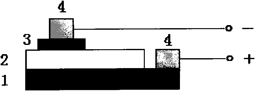
[0043] Such as figure 1 As shown, the pyroelectric thin film material of this embodiment includes Nb:SrTiO from bottom to top 3 Substrate 1, CCTO thin film 2 and gold film 3; The Nb:SrTiO 3 The substrate forms the lower electrode; the gold film forms the upper electrode. The thickness of the CCTO thin film is 500nm-1000nm, and 500nm is taken in this embodiment. The thickness of the gold film is 50nm-60nm, and 50nm is used in this embodiment. The gold film can be prepared into various shapes such as round and square, and only needs to control the area within 0.75mm 2 ~13mm 2 That is, when the planar shape of the gold film is circular, the radius of the gold film is preferably 0.5 mm˜2 mm. This not only facilitates the extraction of the electrodes, but also avoids the conduction of the two electrodes caused by too large a gold film area and too many defects in the covered CCTO film. Both the upper electrode and the lower electrode are led out by bonding wires with silver g...
Embodiment 2
[0053] The structure and manufacturing process of the pyroelectric film in this example are consistent with those in Example 1, the only difference being that in the step (5) of the preparation method, the pyroelectric film in this example is polarized at room temperature for 48 hours. The pyroelectric coefficient of the pyroelectric film of this embodiment is measured, and it can be calculated from the measurement results that the pyroelectric coefficient of the material can reach 1.4×10 in the range of 20°C to 60°C. -7 C / cm 2 ·K.
Embodiment 3
[0055] The structure and manufacturing process of the pyroelectric film of this embodiment are consistent with that of Example 1, the only difference being that in the step (5) of the preparation method, the pyroelectric film of this embodiment is polarized for 72 hours at room temperature, and the The pyroelectric film of the embodiment is measured for the pyroelectric coefficient, and it can be calculated from the measurement results that the pyroelectric coefficient of the material can reach 1.5×10 in the range of 20°C to 60°C. -7 C / cm 2 ·K.
PUM
| Property | Measurement | Unit |
|---|---|---|
| Thickness | aaaaa | aaaaa |
| Radius | aaaaa | aaaaa |
| Pyroelectric coefficient | aaaaa | aaaaa |
Abstract
Description
Claims
Application Information
 - R&D Engineer
- R&D Manager
- IP Professional
- Industry Leading Data Capabilities
- Powerful AI technology
- Patent DNA Extraction
Browse by: Latest US Patents, China's latest patents, Technical Efficacy Thesaurus, Application Domain, Technology Topic, Popular Technical Reports.
© 2024 PatSnap. All rights reserved.Legal|Privacy policy|Modern Slavery Act Transparency Statement|Sitemap|About US| Contact US: help@patsnap.com