
Chilled water direct supply system and method

A technology of chilled water and water pipes, applied in heating and ventilation control systems, heating and ventilation safety systems, air-conditioning systems, etc., can solve the problems of large occupied area and high energy loss rate, achieve convenient installation and transportation, reduce waste, improve The effect of heat exchange efficiency

Inactive Publication Date: 2010-10-20
CHINA CONSTR EIGHT ENG DIV CORP LTD +1
View PDF2 Cites 19 Cited by
  • Summary
  • Abstract
  • Description
  • Claims
  • Application Information

AI Technical Summary

Problems solved by technology

[0008] The purpose of the present invention is to provide a chilled water direct supply system to solve the problems of cost, high energy loss rate and large occupied area of ​​the existing chilled water supply system
[0009] Another object of the present invention is to provide a method for direct supply of chilled water to solve the problems of cost, high energy loss rate and large occupied area of ​​the existing chilled water supply system

Method used


Image

  • Chilled water direct supply system and method
  • Chilled water direct supply system and method
  • Chilled water direct supply system and method

Examples


Embodiment Construction

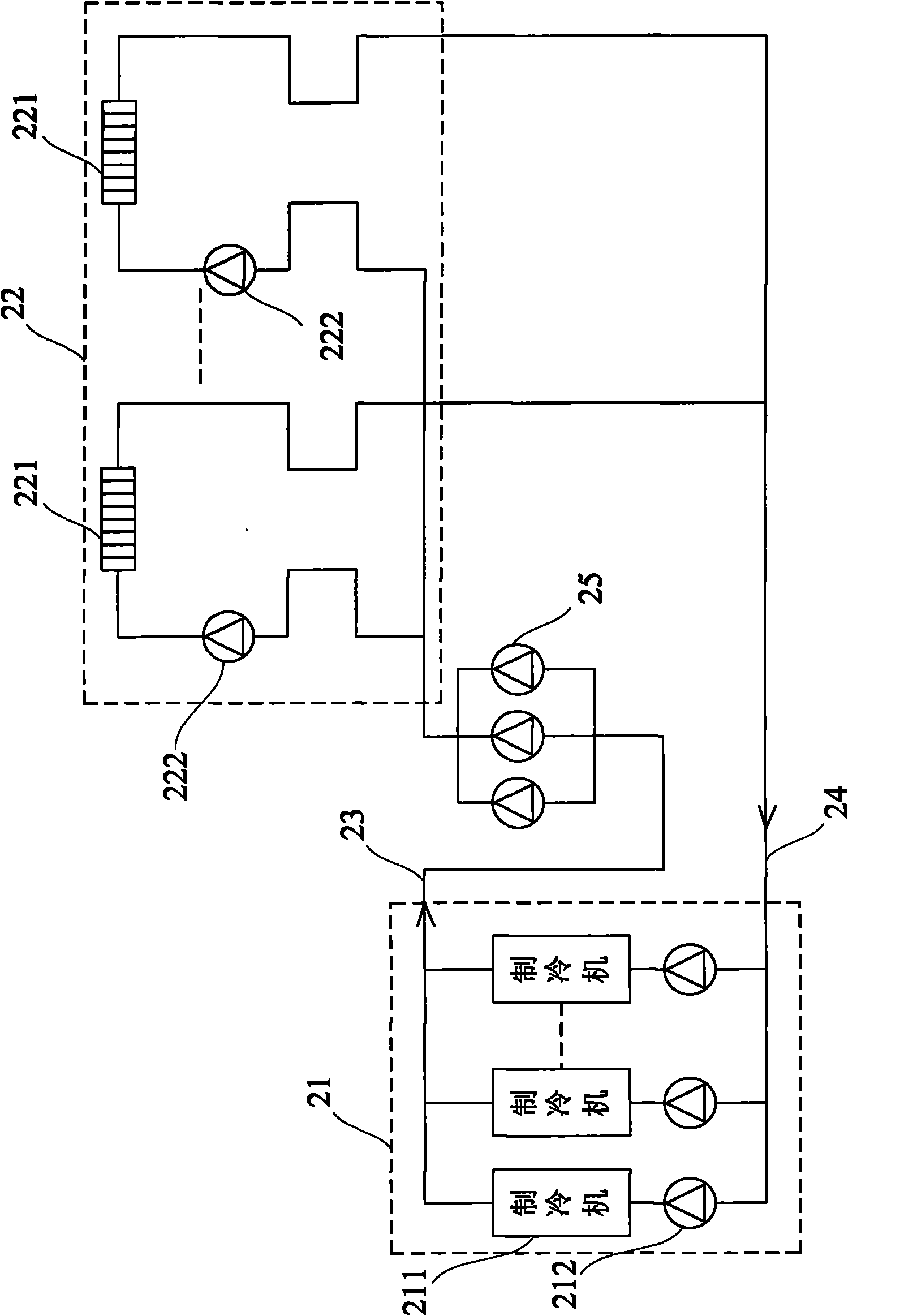
[0033] The main idea of ​​the present invention is to make the chilled water directly enter the end fan coil for heat exchange without going through the plate heat exchanger, so that the construction cost and the operation cost can be greatly saved.

[0034] The present invention will be specifically described below with reference to the accompanying drawings.

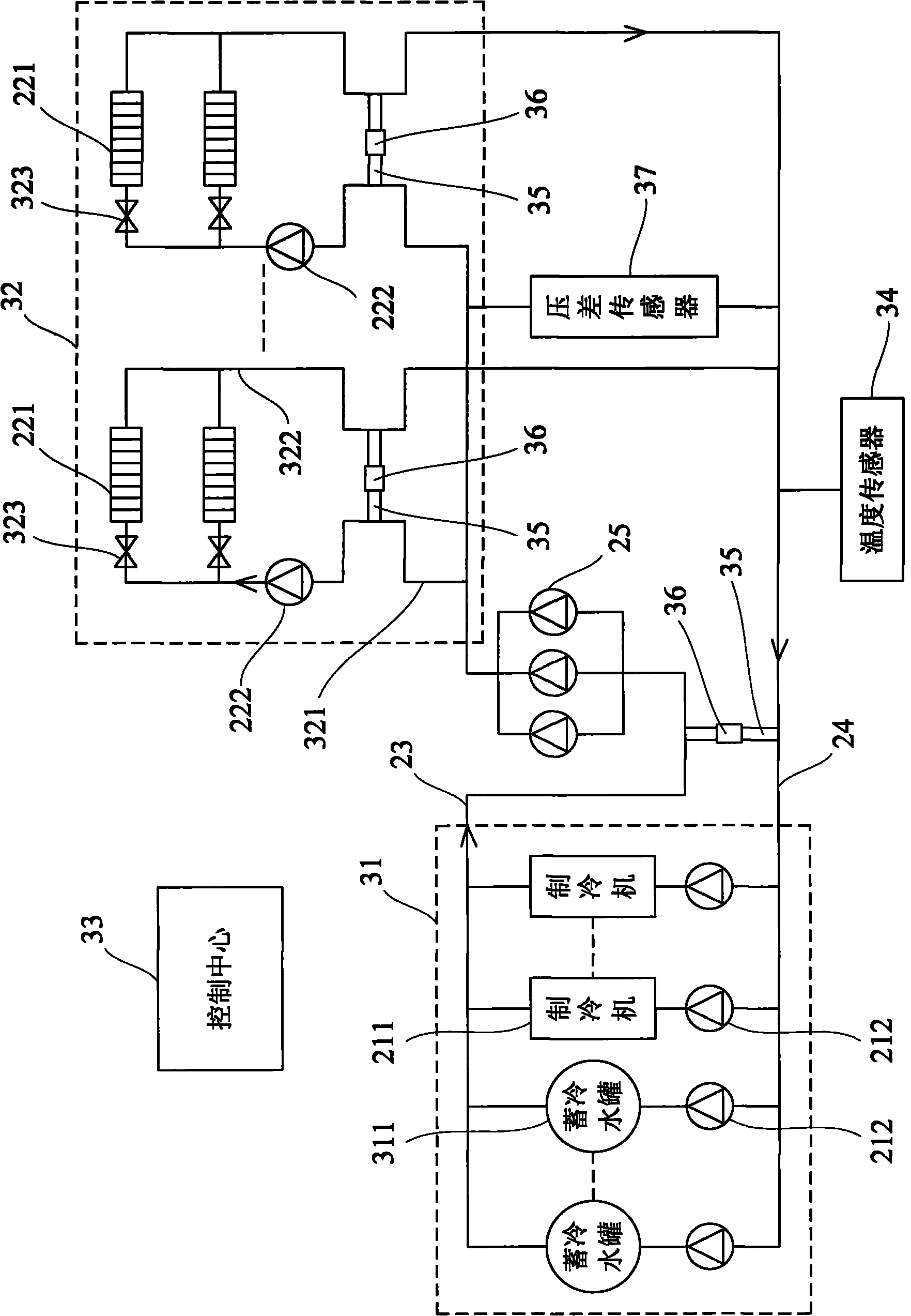
[0035] See figure 2 , which is a structural diagram of an embodiment of the chilled water direct supply system of the present invention. The system includes an energy center 21 and a heat exchange station 22 , and the energy center 21 and the heat exchange station 22 are connected through a main water supply pipe 23 and a main return water pipe 24 . A plurality of parallel secondary pumps 25 are arranged on the main water supply pipe 23, which are used to transport the chilled water output from the energy center 21 to the heat exchange station 22 to consume the cooling capacity.

[0036] Among them, the energy cente...


PUM


Abstract

The invention provides a chilled water direct supply system and a method. The system comprises an energy center, a thermal exchange station and at least one secondary pump; wherein the energy center is connected with the thermal exchange station by a master water supply pipe and a master return pipe. The energy source center, which is composed of at least one refrigerator and at least one primary pump, is used for preparing the chilled water; the refrigerator is in series connection with the primary pump and is arranged between the master water supply pipe and the master return pump. The thermal exchange station, which is composed of at least one draught fan and at least one triplex pump, is used for consuming cooling capacity of the chilled water; the draught fan is in series connection with the triplex pump and is arranged between the master water supply pipe and the master return pipe. The secondary pump arranged on the master water supply pipe is used for transmitting the chilled water outputted from the energy center to the thermal exchange station. The invention has the advantages of low cost and energy loss rate as well as small occupied area.

Description

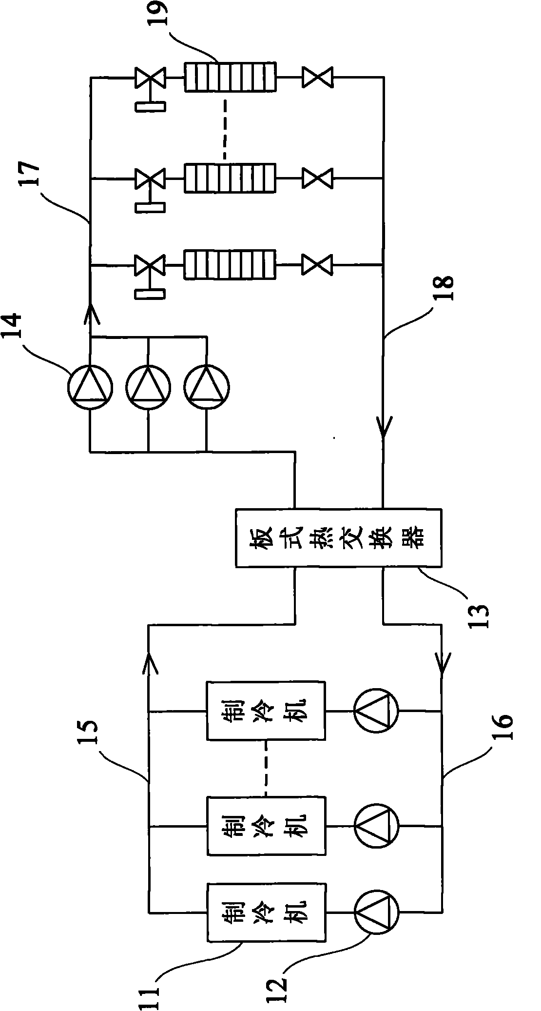
technical field [0001] The invention relates to a refrigeration system, in particular to a chilled water direct supply system and a method thereof. Background technique [0002] At present, the first-stage pump system is generally used in small and medium-sized central air-conditioning projects. When the system is large, the resistance is high, and the load characteristics or resistance of each loop are very different, the secondary pump system is generally used. In the secondary pump system, water pumps are arranged on the cold and heat source side and the load side of the air-conditioning water respectively. The loop; the water pump on the load side is called the secondary pump or the secondary pump, and forms a secondary loop together with the load end equipment, the pipeline system and the bypass pipe. The primary loop is responsible for the preparation of chilled water, and the secondary loop is responsible for the delivery of chilled water. [0003] See figure 1 , ...

Claims


Application Information

Patent Timeline
Patent Type & Authority Applications(China)
IPC IPC(8): F24F3/06F24F11/02
Inventor 赵建春张雷刘涛苗冬梅陈永昌杨柯赵元山吕永峰张海燕曾青高迎军代永军张成林李本勇敖立平芮立平丁锐王勤虎
Owner CHINA CONSTR EIGHT ENG DIV CORP LTD
Learn More