
Great ore drawing simultaneous filling non-top column shrinkage mining method

A mining method and pillar technology are applied in the field of large-scale ore drawing and synchronous filling without pillar ore retention mining, which can solve problems such as funnel blockage, improve ore recovery rate, avoid large-scale movement of surrounding rock and surface subsidence, and expand application. range effect

Inactive Publication Date: 2010-10-20
GUANGXI UNIV
View PDF6 Cites 29 Cited by
  • Summary
  • Abstract
  • Description
  • Claims
  • Application Information

AI Technical Summary

Problems solved by technology

[0006] The technical problem to be solved by the present invention is to overcome the shortcomings of the conventional ore retaining method, such as a large number of fragments and large-scale movement of surrounding rocks, ore depletion, and funnel blockage, which are caused by the increase in the exposed area of ​​surrounding rocks when a large amount of ore is drawn. Give full play to the advantages of the filling material in supporting the two sides and controlling rock movement, and use the vibration ore drawing machine to cooperate with the gravity ore drawing to improve the fluidity of the ore and promote the uniform and synchronous sinking of the filling material and the ore level in the mine house, thus providing a kind of A large-scale ore-drawing synchronous filling without top pillar retention mining method that can effectively control the loss and dilution of ore when drawing a large amount of ore, reduce the clogging rate of the funnel, and limit the large-scale movement of surrounding rocks and surface subsidence

Method used


Image

  • Great ore drawing simultaneous filling non-top column shrinkage mining method
  • Great ore drawing simultaneous filling non-top column shrinkage mining method
  • Great ore drawing simultaneous filling non-top column shrinkage mining method

Examples


Embodiment Construction

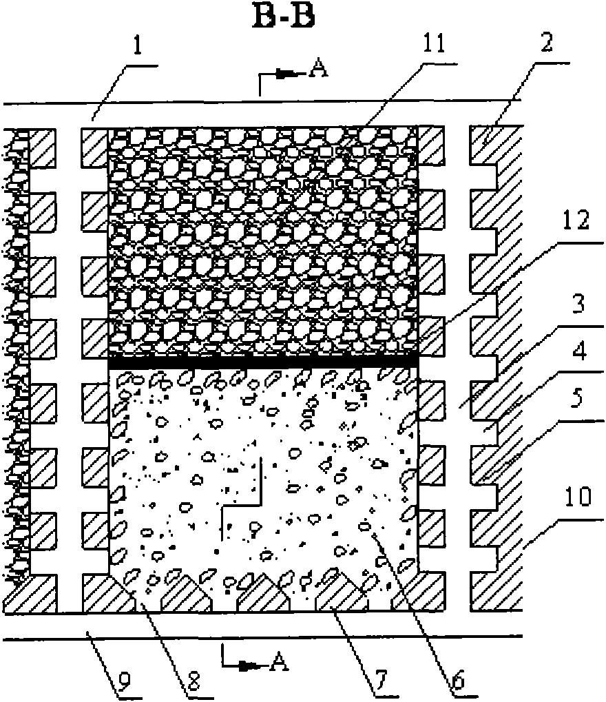
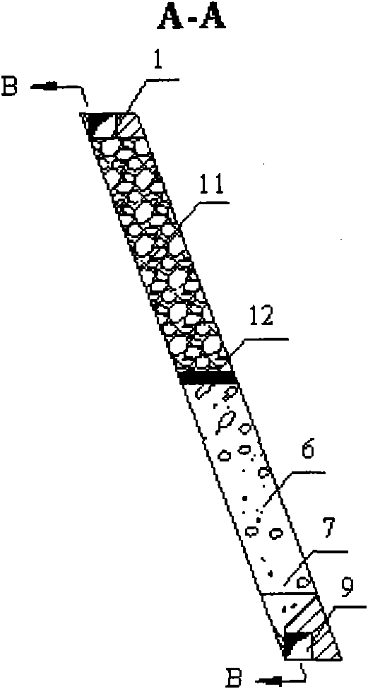
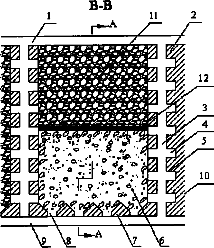
[0024] figure 1 with figure 2 It is a schematic diagram of the mining method of the present invention. A large amount of ore-drawing synchronously filling and mining method without top pillar retention described in the present invention is as follows: firstly divide the steeply inclined thin to medium-thick ore bodies with medium and stable surrounding rocks into stages, and divide the ore blocks within the stages. Firstly, the excavation specification in the inter-column 5 is 2.0×2.0m 2 The advanced patio 3 connects the lower stage transportation roadway 9 with the upper return air roadway 1; the excavation specification in the spacer 5 to the stope is 2.0×1.5m 2 Pedestrian connection roadway 4; digging 2.0×2.0m in the mine 2 The bottom-drawing roadway, the bottom-drawing roadway is used as the free surface brush to form the bottom-drawing space; the funnel 8 is formed downward in the bottom-drawing space, and the vibrating ore-drawing machine is installed at the mouth of...


PUM

PropertyMeasurementUnit
Blockinessaaaaaaaaaa

Abstract

The invention relates to a great ore drawing simultaneous filling non-top column shrinkage mining method which comprises the following steps of: dividing a steep dipping ore body with thin steadiness to medium thick steadiness of surrounding rock above medium steadiness into stages and dividing ore blocks in the stages; stoping ore together with a top column layer by layer from bottom to top according to a traditional shrinkage method in an ore room without retaining the top column; laying an isolating layer on the surface of a shrinkage pile in advance before great ore drawing; drawing dry type paddings with proper lumpiness from an air return tunnel during great ore drawing and carrying out flat field operation in a manual way or an electric scraper way; controlling an ore slipping rate and a padding drawing rate by a vibratory ore-drawing machine matching with weight ore drawing; and simultaneously and uniformly sinking the paddings and the ore and controlling the exposure area of the surrounding rock till the ore is completely drawn. The invention prevents the surrounding rock from greatly scaling and mixing into the ore, controls the dilution rate and the loss rate of the ore, improves the recovery rate of the ore and limits subsidence of the earth surface.

Description

technical field [0001] The invention relates to a mining method for underground mining of metal ore deposits, in particular to a mining method for a large amount of ore drawing and synchronous filling without top pillar retention. It is suitable for the mining of steeply inclined thin to medium-thick ore bodies where the ore is stable and the surrounding rock is moderately stable, the ore does not agglomerate and does not spontaneously combust, the surrounding rock does not allow large-scale movement, and the surface does not allow subsidence. Background technique [0002] There are three main categories of mining methods for metal deposits: open-pit mining, fill-and-fill mining, and caving mining. The open-pit mining method divides the ore block into a mine room and a mine pillar, and mines in two steps. The goaf formed when returning to the mine room is maintained by the strength of the mine pillar and the ore rock itself. The stability of the ore rock is the basic conditi...

Claims


Application Information

Patent Timeline
IPC IPC(8): E21C41/22
Inventor 陈庆发吴仲雄
Owner GUANGXI UNIV
Learn More