Eureka AIR delivers breakthrough ideas for toughest innovation challenges, trusted by R&D personnel around the world.

Real-time monitoring system of offshore ocean floor hypoxia phenomenon

A real-time monitoring system, the underlying technology, applied in transmission systems, testing water, electrical components, etc., can solve the problem of power consumption, anti-interference and scalability with a certain distance, unable to perform real-time monitoring, and difficult to apply ocean hypoxia Monitoring and other issues to avoid mutual interference and improve reliability

Inactive Publication Date: 2010-10-06
SECOND INST OF OCEANOGRAPHY MNR +1
View PDF6 Cites 24 Cited by
  • Summary
  • Abstract
  • Description
  • Claims
  • Application Information

AI Technical Summary

Problems solved by technology

The monitoring system sends the sea bottom water level data to the shore station in real time through wireless transmission and signal relay. There is still a certain distance in terms of anti-interference and scalability, and it is difficult to apply to the monitoring of marine hypoxia
CN100564152C "A Self-sustaining Marine Environment Monitoring System" discloses a marine environment monitoring system comprising a sea surface buoy, a measuring platform and an anchoring system, which can measure water body parameters. However, the monitoring data of the monitoring system adopts self-contained storage, Need to recover the monitoring system to read again, it does not involve data transmission technology, so real-time monitoring cannot be carried out

Method used


Image

  • Real-time monitoring system of offshore ocean floor hypoxia phenomenon
  • Real-time monitoring system of offshore ocean floor hypoxia phenomenon
  • Real-time monitoring system of offshore ocean floor hypoxia phenomenon

Examples


Embodiment

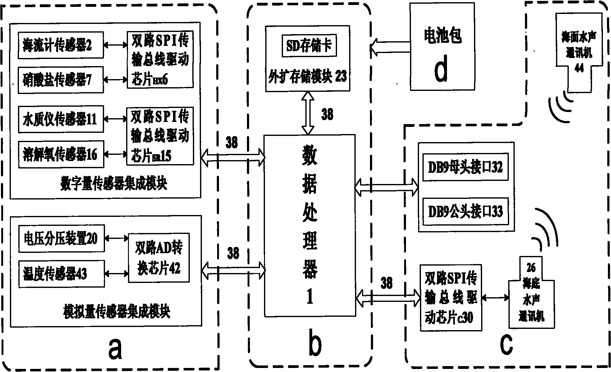
[0074] Example For the peripheral power supply control circuit of the real-time monitoring system for the hypoxia phenomenon of the bottom of the offshore ocean, see Figure 14 , the data processor 1 of the water quality monitoring and control master station b controls whether the 9013 transistor 21 is turned on or not through the P0.10 pin and the current limiting resistor R25. When the 9013 triode 21 is turned on, using the circuit amplification principle of the triode, a large current will flow in the coil of the UB2-4.5NU relay 22, thereby generating a magnetic force to overcome the elastic force of the spring in the relay, turning on the power battery pack d, and realizing external set external power control. The diode D8 in the figure constitutes the discharge circuit of the relay 22 .

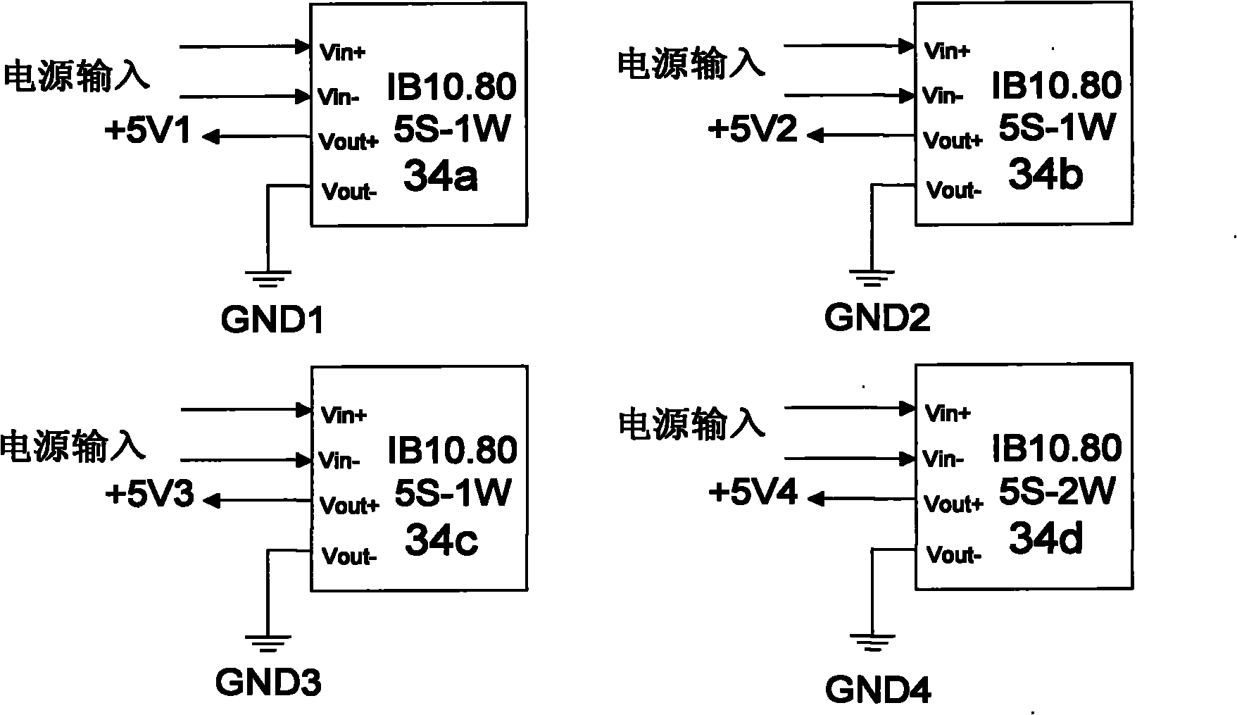
[0075] Embodiment The 3.3V digital power supply of the SD memory card 23, the 3.3V digital power supply of the dual-channel SPI transmission bus driver chip, and the analog power supply...


PUM


Abstract

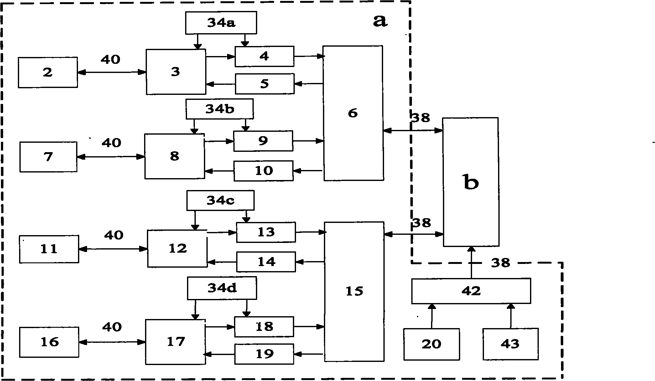
The invention relates to a real-time monitoring system of offshore ocean floor hypoxia phenomenon. The system comprises a water quality monitoring substation, a water quality monitoring main control station, an underwater acoustic communication and 232 serial port communication substation and a battery pack, wherein the water quality monitoring substation comprises a digital sensor integrated module and an analog quantity sensor integrated module; the water quality monitoring main control station comprises a data processor and an outside expanding storage module; the underwater acoustic communication and 232 serial port communication substation comprises a ocean floor underwater acoustic communication machine integrated module, a sea surface underwater acoustic communication machine and a232 serial port communication module; the data processor is connected with the digital sensor integrated module; the analog quantity sensor integrated module, the outside expanding storage module andthe ocean floor underwater acoustic communication machine integrated module through a field transmission bus; the data processor is connected with the 232 serial port communication module through a 232 bus, and the battery pack is connected with the water quality monitoring main control station. The invention has the advantages of safe and convenient operation, low power consumption, strong anti-interference, good expandability, accurate and safe real-time monitoring data and the like.

Description

technical field [0001] The invention relates to an ocean monitoring system, in particular to a real-time monitoring system for the hypoxia phenomenon of the offshore ocean bottom, which is mainly used for real-time and accurate monitoring of water quality parameter data closely related to the hypoxia phenomenon of the offshore ocean bottom. Background technique [0002] The anoxic phenomenon of water bodies with a dissolved oxygen content of ≤2mg / L in the bottom seawater has become one of the major ecological and environmental problems in the world. In the offshore area, especially in the estuary area, the input of a large amount of nutrients and organic matter is easy to cause red tides, and on the other hand, it quickly consumes the dissolved oxygen in the bottom seawater. "Oxygen Zone", also known as "Dead Zone", not only fish, shrimp and shellfish can not survive in these areas, even seagrass can not survive. According to statistics from the United Nations Environment P...

Claims


Application Information

Patent Timeline
Patent Type & Authority Applications(China)
IPC IPC(8): G01N33/18H04B13/02
Inventor 倪晓波黄大吉陈建芳殷建军张礼杰张涛梁楚进项祖丰汤健彬张映波曾定勇
Owner SECOND INST OF OCEANOGRAPHY MNR
Why Eureka
Eureka Blog
Learn More