Device and method for power supply detection

A detection device, voltage detection technology, applied in the direction of measuring devices, measuring electrical variables, measuring current/voltage, etc., can solve problems such as misjudgment of the power supply detection device 100, and achieve a good effect of anti-noise function

Inactive Publication Date: 2010-09-22
FARADAY TECH CORP
View PDF0 Cites 0 Cited by
  • Summary
  • Abstract
  • Description
  • Claims
  • Application Information

AI Technical Summary

Problems solved by technology

Although the difference is less affected by temperature, the difference is also very small, such as 13.99 millivolts (mV), so the device variation characteristics produced under the 65-nanometer process will cause errors in the power supply detection device 100. judge

Method used


Image

  • Device and method for power supply detection
  • Device and method for power supply detection
  • Device and method for power supply detection

Examples


Embodiment Construction

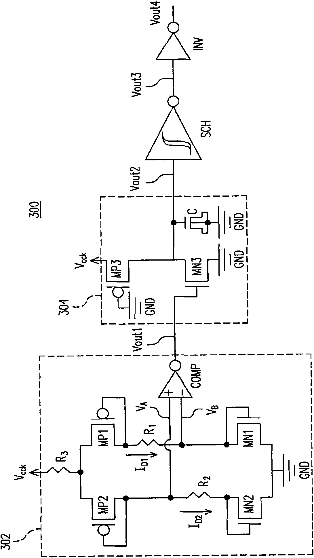
[0039] Please refer to image 3 , image 3 A power supply detection device 300 according to an embodiment of the present invention is shown. The power supply detection device 300 includes a voltage detection unit 302 , a filter 304 , a flip-flop SCH and an inverter INV. Wherein the voltage detection unit 302 receives the input voltage V cck , and detect the input voltage V cckIn order to transmit the output voltage Vout1. In this embodiment, the trigger SCH may be a Schmitt trigger. Furthermore, the voltage detection unit 302 includes two PMOS transistors MP1 and MP2, two NMOS transistors MN1 and MN2, three resistors R 1 , R 2 with R 3 , and the comparator COMP, where the current I D1 for the flow through the resistor R 1 current, while the current I D2 for the flow through the resistor R 2 current.

[0040] Resistance R 3 One end is coupled to the input voltage V cck , and the other end is coupled to the source of the PMOS transistor MP1 and the source of the PMO...


PUM


Abstract

The invention discloses a device and a method for power supply detection. The device for power supply detection comprises four transistors, two resistors and a comparator for detecting input voltage and judging whether to start up. The judging process can be hardly affected by temperature. The device is stable at different temperature conditions and has good anti-noise performance.

Description

technical field [0001] The present invention relates to a power supply detection device, and in particular to a power supply detection device with temperature immunity. Background technique [0002] On many electronic devices and circuits, a power supply detection device is usually installed to detect whether the external power supply is actually powered. For example, when the power supply rises to the threshold value of 1 volt (V), the power supply detection device should judge that it is powered on . However, under the design requirements for energy saving and manufacturing process of consumer electronic devices, the threshold volts are getting smaller and smaller, and the size of the manufacturing process is getting smaller and smaller. At this time, the circuit of the power supply detection device will be affected by the temperature. It will be misjudged when starting up. Known power supply detection devices include bandgap type and P / N device plus resistance (P / N devi...

Claims


Application Information

Patent Timeline
Patent Type & Authority Applications(China)
IPC IPC(8): G01R19/00
Inventor 高永信连南钧
Owner FARADAY TECH CORP
Why Eureka
Try Eureka