
Device for measuring spectral responsivity of infrared photoelectric detector

An infrared detector, spectral response technology, applied in measurement devices, optical radiation measurement, spectrometry/spectrophotometry/monochromator, etc., can solve problems such as single function

Inactive Publication Date: 2010-09-22
XIAN TECHNOLOGICAL UNIV
View PDF0 Cites 15 Cited by
  • Summary
  • Abstract
  • Description
  • Claims
  • Application Information

AI Technical Summary

Problems solved by technology

[0003] The technical problem to be solved by the present invention is to provide a responsivity measuring device of an infrared detector, which can measure the spectral responsivity of an infrared photodetector without affecting the measurement function of a Fourier infrared spectrometer, so as to solve the problem of existing Fourier infrared spectrometers. The leaf infrared spectrometer has a single function and cannot be directly used for the measurement of the spectral responsivity of the infrared photodetector

Method used


Image

  • Device for measuring spectral responsivity of infrared photoelectric detector
  • Device for measuring spectral responsivity of infrared photoelectric detector

Examples


Embodiment 1

[0014] Measuring the spectral radiant power of the infrared light source:

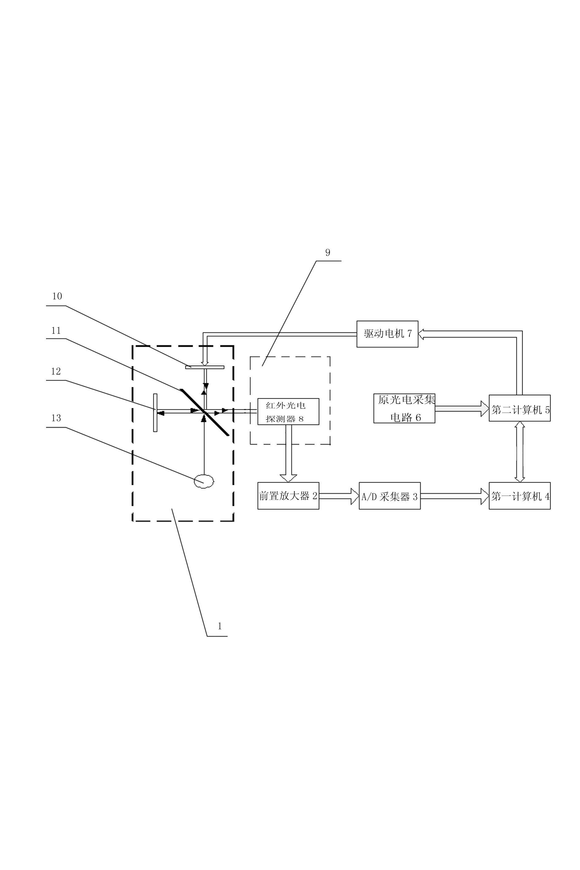
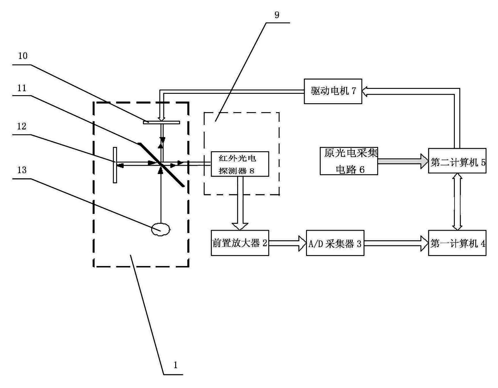
[0015] Place the preamplifier 2 in the sample chamber 8 of the Fourier infrared spectrometer and know the infrared spectral response rate (S 0 ) Curved red photoelectric external detector (infrared detector is a standard detector for calibrating the radiation power of the light source), the output of the preamplifier 2 is connected to the input of the A / D collector through the BNC cable, and the A / D collector 3 passes The PCI bus is plugged into the A / D acquisition board of the second computer, and then the control software configured by the first computer 5 and the measurement software of the Fourier infrared spectrometer on the second computer 4 are respectively run. The first computer 5 passes the control software Capture the synchronization signal driving the motion of the moving mirror, and then trigger the second computer 4 to collect the voltage signal converted by the infrared detector through the ...

Embodiment 2

[0018] Measuring the spectral response rate of infrared detectors:

[0019] The difference from embodiment 1 is that the sample chamber 8 is equipped with the infrared photodetector under test and its corresponding preamplifier. The other measurement process is the same as that in embodiment 1. At this time, the second computer can obtain the infrared photodetector under test. The spectral response voltage signal U x , And then calculate the spectral response rate S of the infrared photodetector under test according to the following formula x :

[0020] S x =U x / P=S 0 U x / U 0 .

Embodiment 3

[0022] Measure the spectral responsivity of the refrigerated quantum well infrared detector:

[0023] The difference from Example 1 is that the sample chamber 8 is equipped with a cold finger part equipped with a quantum well infrared detector (the quantum well infrared detector is placed in the refrigerator), and the refrigerator is equipped with a corresponding quantum well infrared detector. The preamplifier (a black-painted outer cover on the inner wall can be made to shield the ambient light), and then the spectral responsivity of the refrigerated quantum well infrared detector is measured according to the steps in Example 2.

[0024]


PUM


Abstract

The invention relates to a device for measuring the spectral responsivity of an infrared photoelectric detector. Most current Fourier transform infrared spectrometers cannot be directly used for measuring the spectral responsivity of the infrared photoelectric detector. The device for measuring spectral responsivity of the infrared photoelectric detector comprises a Fourier transform infrared spectrometer which comprises a Michelson interferometer, a sample room, a first computer, an infrared photoelectric detector, a preamplifier and a second computer. The infrared photoelectric detector and preamplifier are arranged in the sample room. The arranging position of the infrared photoelectric detector ensures that the photosurface can receive the interference intensity signal emitted by the Michelson interferometer. The infrared photoelectric detector is connected with the second computer via the preamplifier and an A / D collector, and the second computer is in communication connection with the first computer. In the invention, the Fourier transform infrared spectrometer can not only be used to measure the spectral responsivity but also have the previous function of measurement.

Description

technical field [0001] The invention belongs to the technical field of infrared photodetector testing, and specifically refers to a spectral responsivity measuring device of an infrared detector. Background technique [0002] Spectral responsivity is an important characteristic parameter of infrared detectors. Generally, there are two methods for measuring the spectral responsivity of infrared detectors: the monochromator method and the Fourier transform method. The design is difficult and it is difficult to achieve the desired effect; the Fourier transform method uses the correspondence between the interferogram and the spectrogram to measure the infrared spectral response of the detector by measuring the interferogram and performing Fourier transform on the interferogram. This method has fast measurement speed, high signal-to-noise ratio, large luminous flux, high wavenumber accuracy, wide spectral range, and high resolution; To analyze the composition of the sample or t...

Claims


Application Information

Patent Timeline
Patent Type & Authority Applications(China)
IPC IPC(8): G01J3/28G01J3/02
Inventor 高爱华刘卫国秦文罡张佩吕祥
Owner XIAN TECHNOLOGICAL UNIV
Learn More