Acousto-optic automatic target reporting system
An automatic, acousto-optic technology, applied in target indication systems, targets, offensive equipment, etc., can solve the problems of undiscovered reports or documents, achieve flexible and convenient deployment, reduce manufacturing costs, and reduce machining accuracy.
- Summary
- Abstract
- Description
- Claims
- Application Information
AI Technical Summary
Problems solved by technology
Method used
Image
Examples
Embodiment 1
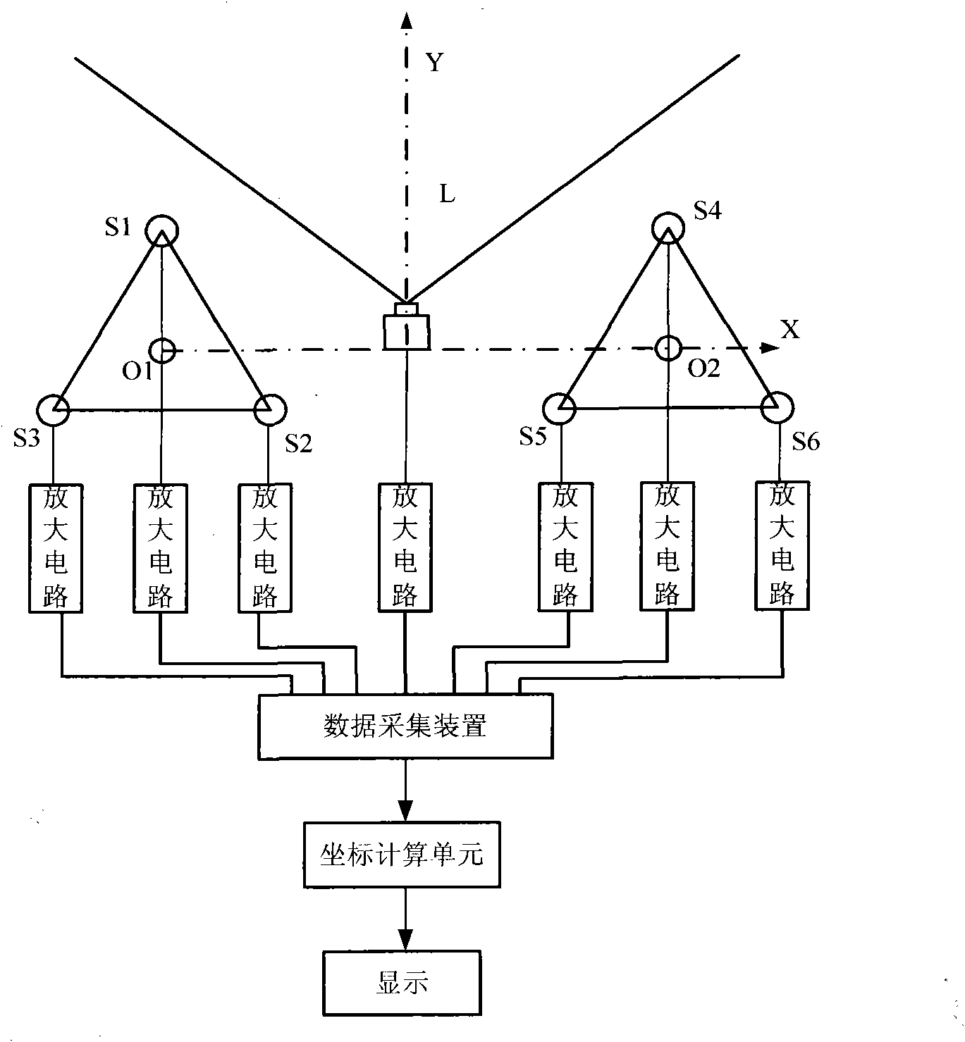
[0028] Embodiment 1: see figure 1 , the present invention is an acousto-optic automatic target reporting system, comprising: a detection light curtain L, an amplifying circuit, a data acquisition device, a coordinate calculation unit and a display part, and the present invention also includes a microphone array, and the detection light curtain L and the microphone array simultaneously The flying projectile is measured, and the captured signals are transmitted to the data acquisition device through their respective amplifiers, and the target information of the measured flying projectile is given; when the supersonic flying projectile passes through the detection light curtain, the detection light curtain outputs a trigger pulse to make The data acquisition device starts to work, and then the shock wave signal generated by the supersonic flying projectile is detected by the microphone array and outputs a corresponding signal. According to the time value of each microphone in the...
Embodiment 2
[0031] Embodiment 2: the main body constitutes the same as embodiment 1, see figure 1 .
[0032] The sound and light automatic target reporting system has two microphone arrays, and each microphone array is composed of three microphones. Microphone S1, microphone S2, and microphone S3 form the first microphone array, and microphone S4, microphone S5, and microphone S6 form the second microphone array. , the two microphone arrays are in the same plane as the detection light curtain L.
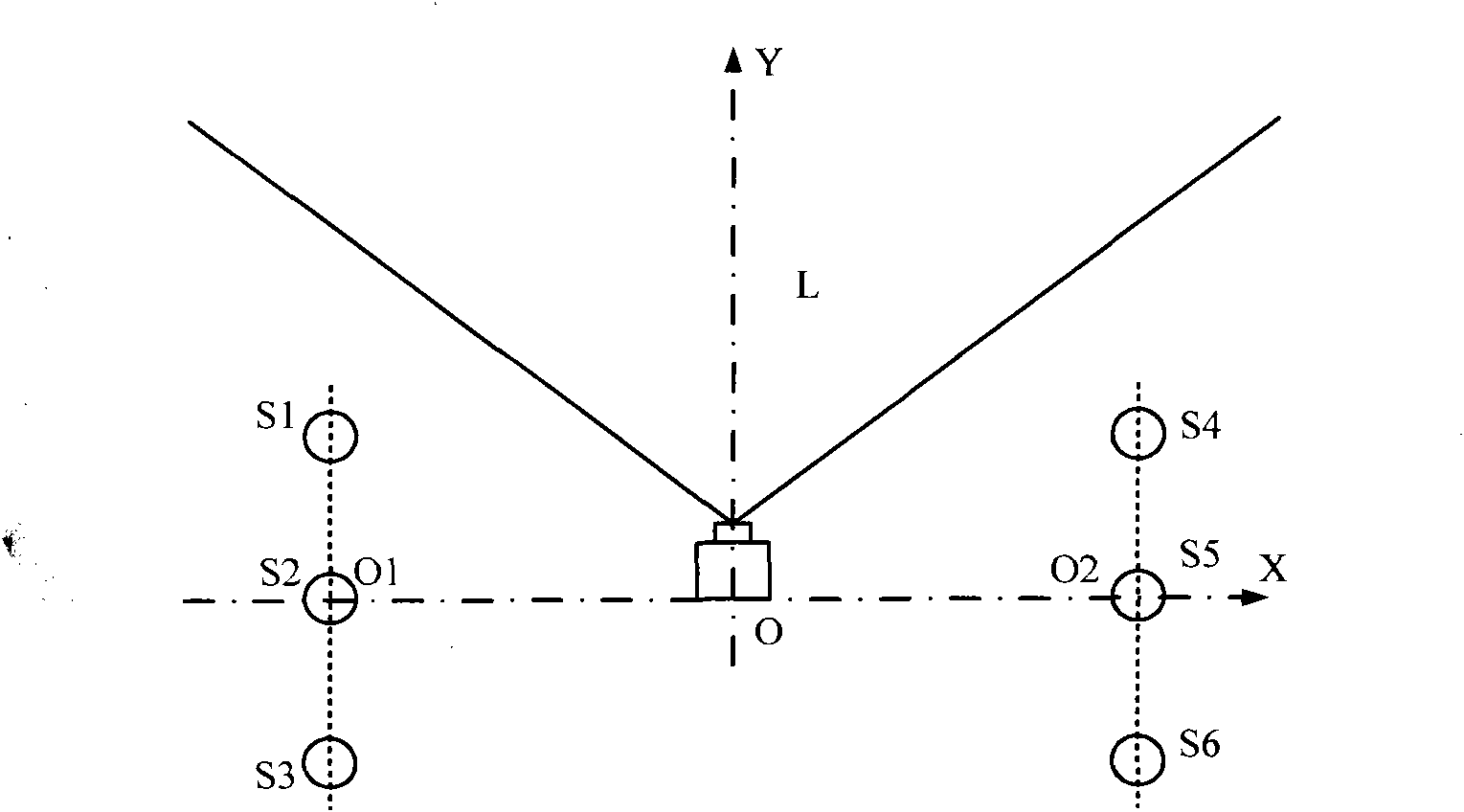
[0033] The invention has no special requirements on the position of the microphone in the sound array, which greatly reduces the installation requirements of the microphone and the machining precision of the microphone fixing device, and reduces the manufacturing cost of the whole system.
Embodiment 3
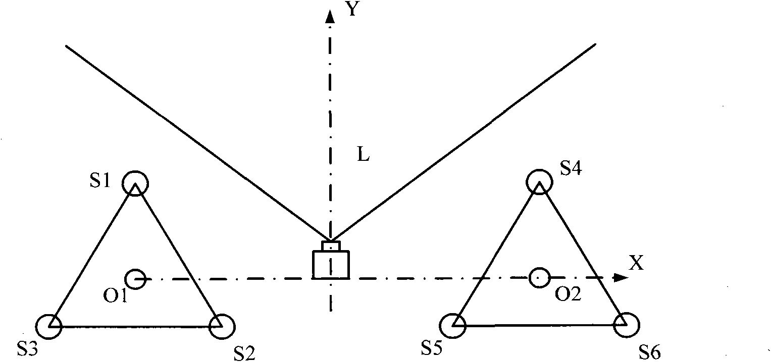
[0034] Embodiment 3: The composition of the main body is the same as in Embodiment 2. The layout of the two microphone arrays of the automatic target reporting system is: the connection line of the three microphones is a triangle, and the arrangement rule of the microphones is that the three microphones are arranged around the center point of the array, and the three microphones are arranged around the center point of the array. The wiring of the microphones forms a triangular combination array. see figure 2. In this example, the triangle of the microphone array is a regular triangle. In the first microphone array, microphone S1, microphone S2, and microphone S3 are located around the center point 01 of the array, all of which are equidistant from the center point 01 of the array. The connection of microphone S1, microphone S2, and microphone S3 Lines form regular triangle combinations.
PUM
 Abstract
Description
Claims
Application Information
 - R&D
- Intellectual Property
- Life Sciences
- Materials
- Tech Scout
- Unparalleled Data Quality
- Higher Quality Content
- 60% Fewer Hallucinations
Browse by: Latest US Patents, China's latest patents, Technical Efficacy Thesaurus, Application Domain, Technology Topic, Popular Technical Reports.
© 2025 PatSnap. All rights reserved.Legal|Privacy policy|Modern Slavery Act Transparency Statement|Sitemap|About US| Contact US: help@patsnap.com


