Method for melting glass

A glass and melting zone technology, applied in glass furnace equipment, glass manufacturing equipment, manufacturing tools, etc., can solve the problems of increased powder fuel consumption, reduced burner efficiency, and no formation of vanadium pentoxide and alumina

Inactive Publication Date: 2010-09-15
VITRO GLOBAL
View PDF11 Cites 1 Cited by
  • Summary
  • Abstract
  • Description
  • Claims
  • Application Information

AI Technical Summary

Problems solved by technology

[0029] 2. No evidence of the formation of vanadium pentoxide and alumina or vanadium pentoxide and silica crystalline compounds or solid solutions was found
However, it has been found that by using the actual burner, a secondary air must be used to mix with the pulverized fuel-air or gas mixture, all of which create heat loss in the combustion cycle and as a result the burner efficiency is reduced
[0065] The applicant believes that the above heat loss is due to the entry of cold air for cooling, so the consumption of pulverized fuel is significantly increased, and as a result, more CO gas is produced after combustion

Method used


Image

  • Method for melting glass
  • Method for melting glass
  • Method for melting glass

Examples


Embodiment Construction

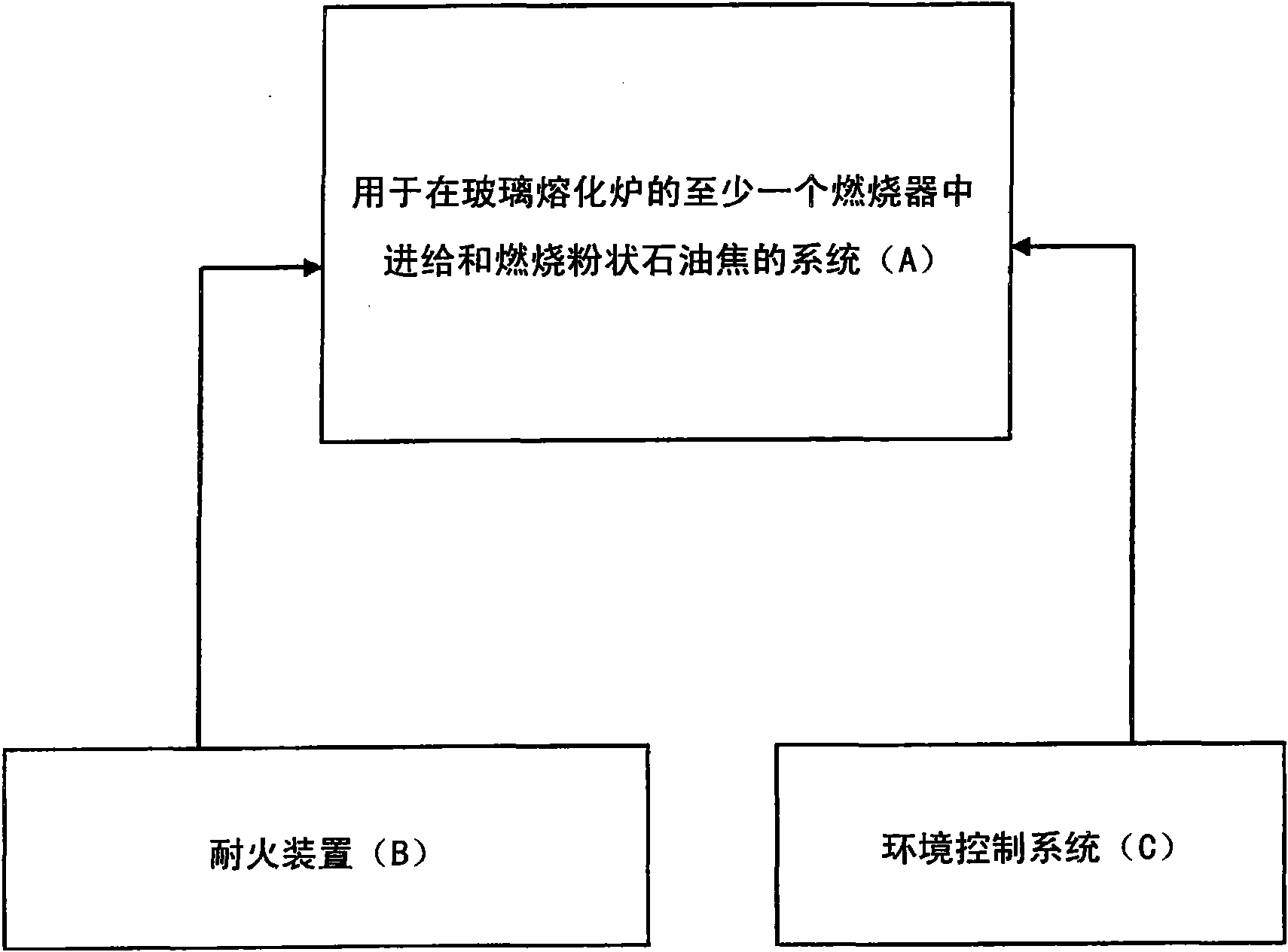
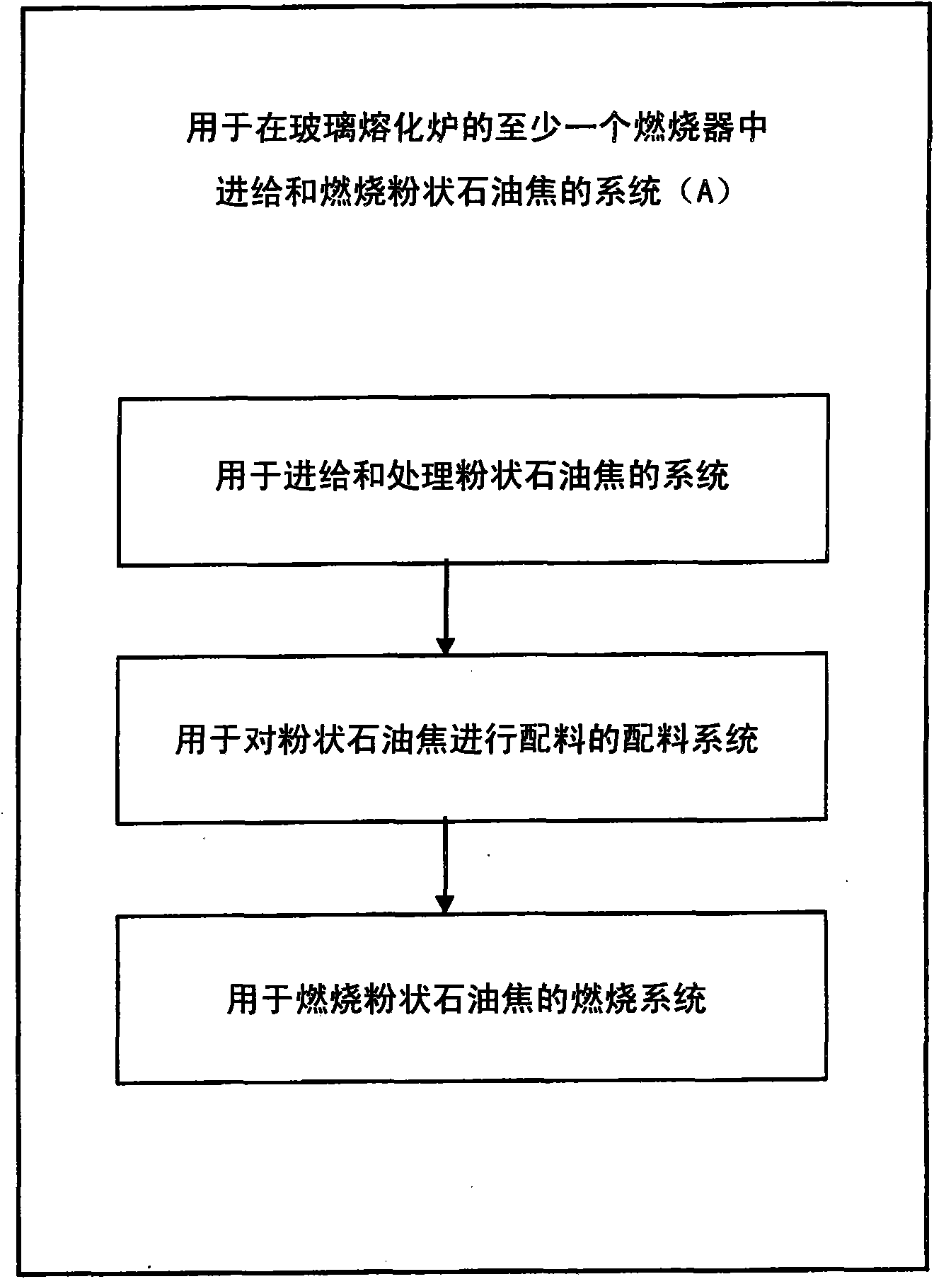
[0087] The present invention will be described below in conjunction with specific embodiments, wherein the same components will use the same reference numerals, figure 1 is a block diagram of an embodiment of the present invention, which mainly includes a system for supplying and burning pulverized fuel in at least one burner A of a side port glass melting furnace, which will be described later. The refractory device B of different shapes is used to form the wall, bottom and top of the glass melting furnace, the wall, bottom and top of the different combustion ports where the burner is arranged, and the wall, top and filler of the lattice body of the regenerator cavity, and the refractory The device is selected from silica, alumina, zircon, magnesite, chromium, ceramic, alumina-silicate, zircon-silicate, magnesia, or mixtures thereof. For example, the refractories are manufactured from: pressed silica, fused silica, direct cast silica; fusion cast alumina-silica-zircon; presse...


PUM


Abstract

The present invention is related to a method for the combustion of pulverized fuel as a heating source for melting raw materials for producing glass. The method including the steps of, feeding a regulated controlled flow of a mixture of pulverized fuel and air or gas under pressure for pneumatic transport in at least one distribution means; discharging the mixture of pulverized fuel and air or gas from feeding means toward at least one of said distribution means; regulating in a controlled manner the pulverized fuel-air or gas mixture from the distribution means to each of a plurality of burners in a glass melting region of a glass melting furnace; burning the pulverized fuel by means of the burners in the glass melting region of said glass melting furnace while providing a combustion flame with high thermal efficiency to carry out a controlled heating for melting the glass; and, counteracting erosive and abrasive effects of the pulverized fuel in the glass melting furnace by means of refractory materials. The refractory materials being selected of silica-alumina-zircon, magnesite, chrome-magnesite, magnesia-alumina spinel, alumina-silicate, zircon-silicate, magnesium oxide silica or alumina mixtures of the same.

Description

technical field [0001] The present invention relates to a method for melting glass, and more particularly, the present invention relates to a method for melting glass using pulverized fuel. Background technique [0002] Glass can be melted in different types of melting furnaces and with different types of fuels, depending on the final properties of the product and taking into account the thermal efficiency of the melting and refining process. Unit furnaces can be used to melt glass (by gaseous fuel), these furnaces have multiple burners along their sides, the whole unit looks like a closed box with a chimney on the box, the chimney can be placed on the feed At the starting position of the device or at the endmost position of the furnace, this means proceeding downstream. However, a large heat loss occurs when the glass leaves the high temperature furnace. For example, at 2500°F, the heat in the flue gas accounts for 62% of the heat input to a natural gas fired furnace. ...

Claims


Application Information

Patent Timeline
Patent Type & Authority Applications(China)
IPC IPC(8): C03B5/235C03B5/43
CPCC03B5/235C03B5/43
Inventor M·A·奥林努涅斯R·卡布雷拉利亚诺斯I·J·索利斯马丁内斯R·巴拉德斯卡斯蒂略
Owner VITRO GLOBAL
Why Eureka
Try Eureka