Birdcage coil with improved homogeneity and reduced SAR

A technology of coils and bird cages, applied in the field of subject imaging systems, can solve the problems of reducing the length of crosspieces, achieve a large usable range, and improve the effect of axial uniformity

Inactive Publication Date: 2010-09-08
KONINKLIJKE PHILIPS ELECTRONICS NV
View PDF5 Cites 4 Cited by
  • Summary
  • Abstract
  • Description
  • Claims
  • Application Information

AI Technical Summary

Problems solved by technology

[0003] However, a limitation of this type of design is that the rung width and end ring width can only be increased before image degradation begins to occur
In other words, widening the end rings reduces the effective rung length when the overall length of the birdcage coil is already fixed for other structural reasons

Method used


Image

  • Birdcage coil with improved homogeneity and reduced SAR
  • Birdcage coil with improved homogeneity and reduced SAR
  • Birdcage coil with improved homogeneity and reduced SAR

Examples


Embodiment Construction

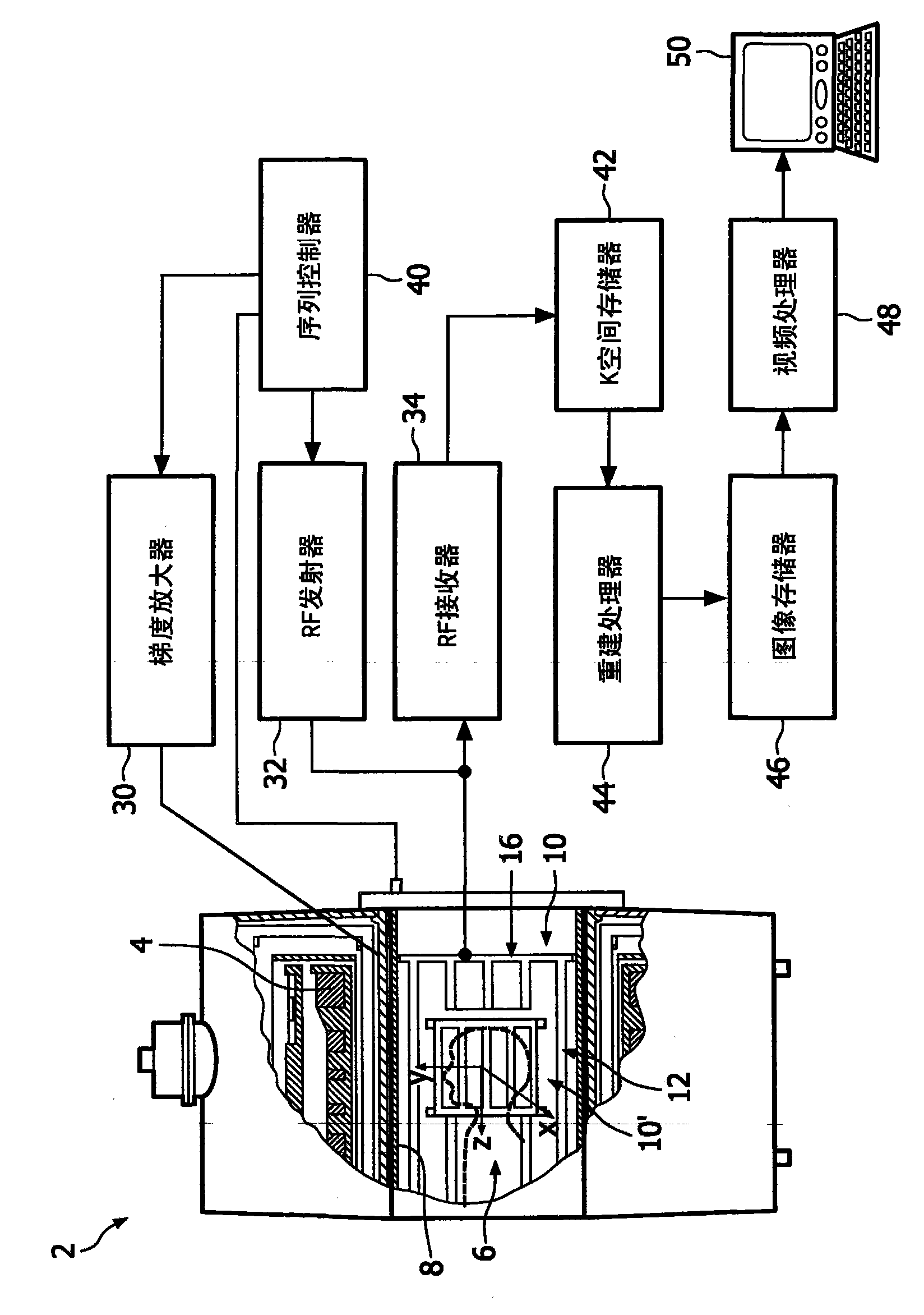
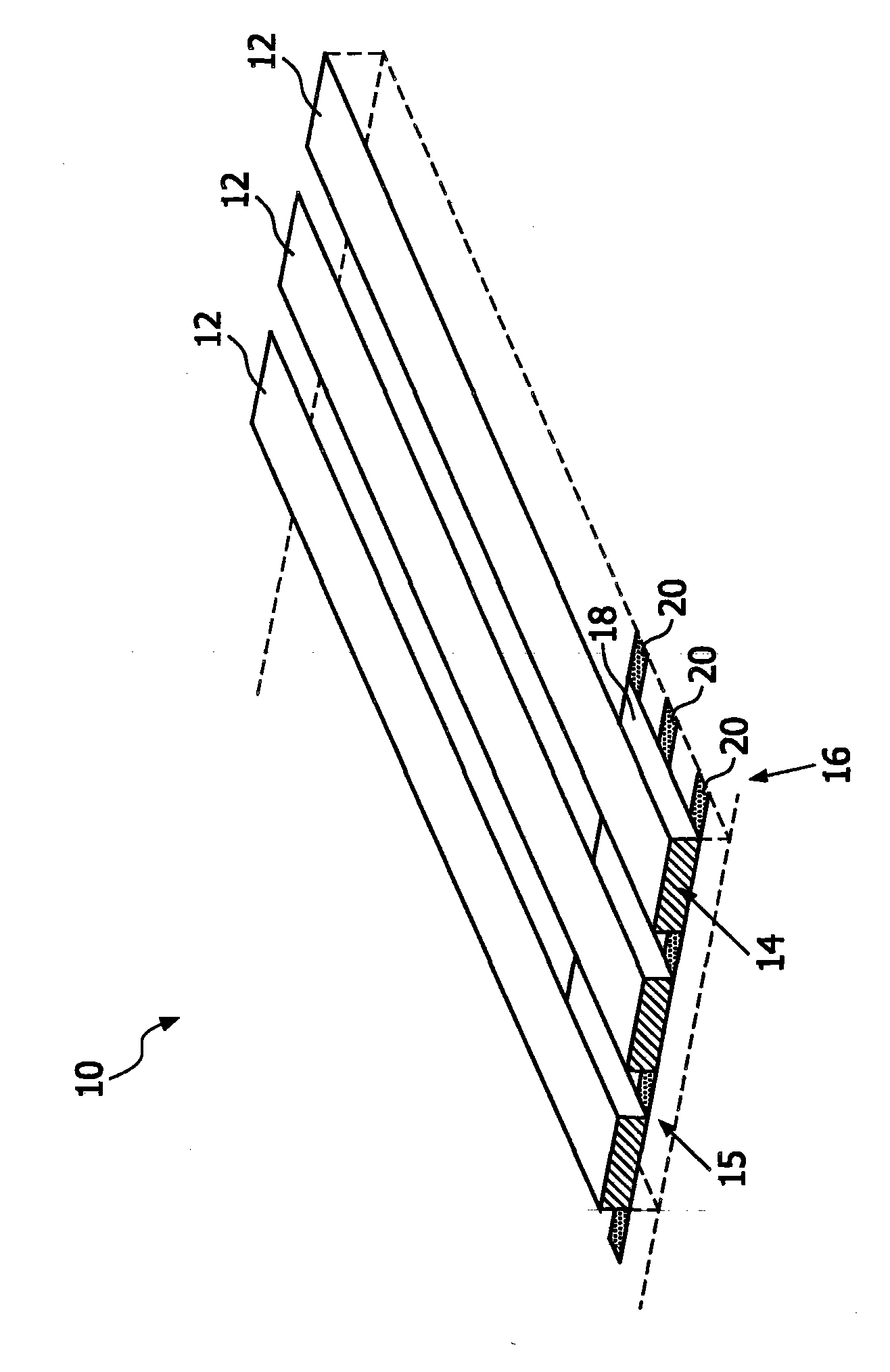
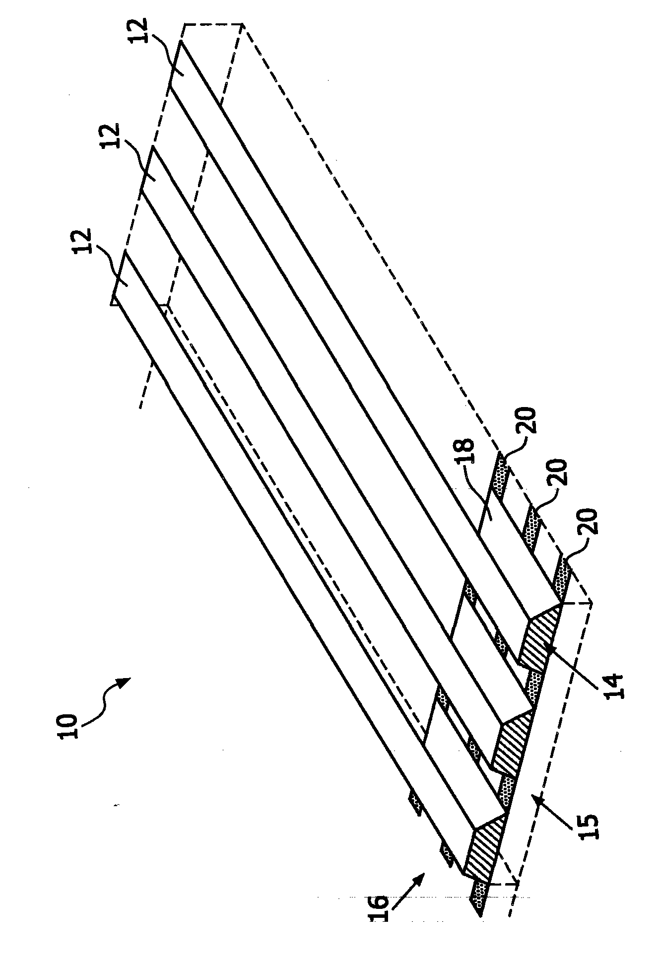
[0021] The systems and methods described herein facilitate improving sensitivity and uniformity while reducing SAR of birdcage coils of magnetic resonance imaging (MRI) systems, as well as improving coil performance using various design features. According to various aspects, the rungs of the birdcage coils are coupled to the distal (e.g., relative to the center of the birdcage coil) edges of the end rings, rather than to the ends of the end rings as conventional birdcage coils are typically coupled. inner edge. This allows tighter coils to be produced while maximizing or optimizing rung length and end ring width. The structure described herein thus reduces the birdcage length by twice the width of the end ring. Furthermore, the described coil structure can help to reduce the "effective volume" of the coil and achieve a correspondingly higher power sensitivity.

[0022] Refer to attached figure 1 , illustrates a magnetic resonance (MR) scanner 2 capable of employing the var...


PUM


Abstract

A birdcage coil (10) for a magnetic resonance imaging device includes a plurality of rungs (12) coupled to a distal edge (15) of each of two endrings (16). The endrings (16) comprise a plurality of ring segments (18) that are separated by sets of capacitors (20, 22, 24). The rungs (12) are coupled to the endrings (16) by connector portions (14), which create a gap between the endrings (16) and the rungs (12). Additionally, the rungs (12) can be positioned over the capacitors (20, 22, 24), and the connector portions (14) can be shaped to offset the position of the rungs (12) relative to the ring segments (16) to which they are coupled to achieve a desire rung position relative to the capacitors (20, 22, 24).

Description

technical field [0001] The present application finds particular application in subject imaging systems, in particular magnetic resonance imaging (MRI). However, it should be appreciated that the described techniques may also be applied to other imaging systems, other medical protocols, or other medical techniques. Background technique [0002] Conventional birdcage coil designs employ rungs and end rings in the form of flat metal strips attached to a load-bearing structure. It has been found that wide rungs and wider rings facilitate high power sensitivity. When the end rings are placed closer to the radio frequency (RF) shield than the rungs, the uniformity of the RF magnetic field is improved and the patient's specific absorption rate (SAR) is reduced. See, for example, "An Elevated Endring Birdcage Coil for Improved Performance at 3 Tesla" (D. Weyers, D. Keren, E. Boskamp, ​​G. McKinnon, K. Kinsey, Proc. Intl. Soc. Mag. Reson. Med. 2004 November, p. 1548); US Patent Ap...

Claims


Application Information

Patent Timeline
Patent Type & Authority Applications(China)
IPC IPC(8): G01R33/34
CPCG01R33/34076G01R33/288G01R33/34007G01R33/422
Inventor K-M·吕德克
Owner KONINKLIJKE PHILIPS ELECTRONICS NV
Why Eureka
Try Eureka