Upper suction compact spinning ring bobbin

A technology of compact spinning and spinning frames, which is applied to spinning machines, continuous winding spinning machines, textiles and papermaking, etc. It can solve the problems of inability to meet the negative pressure requirements of compact spinning and large negative pressure difference, and achieve operation and Low maintenance cost, small negative pressure difference and low installation cost

Inactive Publication Date: 2010-09-08
JINGWEI TEXTILE MASCH CO LTD
View PDF8 Cites 0 Cited by
  • Summary
  • Abstract
  • Description
  • Claims
  • Application Information

AI Technical Summary

Problems solved by technology

However, with the increase in the number of spindles and the lengthening of the suction pipe, the negative pressure difference between the front and the rear of the car is getting larger and larger, which cannot meet the negative pressure requirements of compact spinning. Therefore, the current domestic compact spinning long cars still use small fans. negative pressure system

Method used


Image

  • Upper suction compact spinning ring bobbin
  • Upper suction compact spinning ring bobbin

Examples


Embodiment Construction

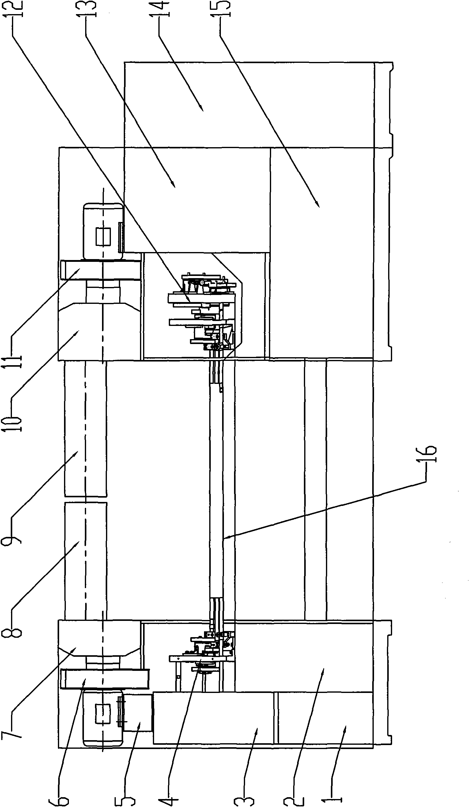
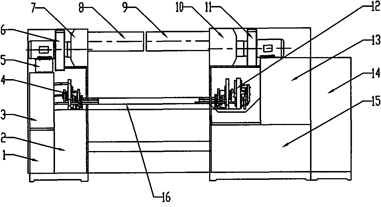
[0011] A top-suction compact spinning ring spinning machine, which includes a lifting part 1, a lifting distribution part 2, a gear transmission part 3, a headstock drafting part 4, a headstock compact spinning fan mounting seat 5, a headstock compact spinning fan 6, and a headstock compact spinning machine. Spinning bellows 7, headstock compact spinning suction pipe 8, rear compact spinning suction pipe 9, rear compact spinning bellows 10, rear compact spinning fan 11, rear drafting parts 12, cotton suction bellows 13, electric control cabinet 14. The main transmission part 15 and the middle part 16 of the compact spinning frame, the lifting part 1 is set on the spinning machine head, the lifting distribution part 2 is set on the right side of the lifting part 1, the gear transmission part 3 is set on the top of the lifting part 1, The headstock drafting part 4 is arranged on the top of the lifting distribution part 2 and connected with the gear transmission part 3, the headst...


PUM


Abstract

The invention relates to an upper suction compact spinning ring bobbin. A headstock drafting component (4) is arranged at the top of a lifting distribution component (2) and is connected with a gear transmission component (3); a headstock compact spinning air blower (6) is arranged on a headstock compact spinning air blower installing seat (5); a headstock compact spinning air box (7) is arranged at the top of the headstock drafting component (4) and is connected with the headstock compact spinning air blower (6); a headstock compact spinning air suction pipe (8) is arranged above a middle section part (16) of a compact spinning machine and is connected with the headstock compact spinning air box (7); a tailstock drafting component (12) and a cotton sucking air box (13) are arranged on a main transmission component (15); a tailstock compact spinning air blower (11) is arranged on the cotton sucking air box (13); a tailstock compact spinning air box (10) is arranged above the tailstock drafting component (12) and is connected with the tailstock compact spinning air blower (11); and a tailstock compact spinning air suction pipe (9) is arranged above the middle section part (16) of the compact spinning machine and is connected with the tailstock compact spinning air box (10). The invention has the advantages of small negative pressure difference, constant negative pressure and high reliability, can ensure high quality of yarn, and is suitable for compact spinning long vehicles.

Description

technical field [0001] The invention belongs to textile machinery, in particular to an updraft compact spinning ring spinning machine. Background technique [0002] The ring spinning frame is an important equipment with a large area and a wide range of production processes in the textile industry. After 10 years of development, the compact spinning technology has become a mature technology. The compact spinning frame has formed a certain scale. With the continuous improvement of human living standards , the demand for compact yarn is increasing, and there is a very large market demand for compact spinning frame and compact spinning transformation. [0003] At present, there are five compact spinning systems represented by Rieter, Sussen, Zinser, Toyota and Rocos1 in the world. The principle of compact spinning is to increase the fiber accumulation area after the main drafting area, so that the drafting does not accumulate, and the accumulation does not draw. The sliver has...

Claims


Application Information

Patent Timeline
Patent Type & Authority Applications(China)
IPC IPC(8): D01H1/02D01H5/72
Inventor 张新民师雅并田克勤谈叡石华睿李嘉琦王峰山张满枝剌志勇王建根
Owner JINGWEI TEXTILE MASCH CO LTD
Why Eureka
Try Eureka