Boomerang

A technology of darts and blades, applied in the field of boomerangs, can solve problems such as complex toys, achieve long flight time, increase kinetic energy, and simple structure

Active Publication Date: 2010-09-01
TOSY ROBOTICS
View PDF2 Cites 5 Cited by
  • Summary
  • Abstract
  • Description
  • Claims
  • Application Information

AI Technical Summary

Problems solved by technology

[0004] However, these toys appear to be rather complex, they require an elevation control that changes the angle according to the rotational speed of the blades

Method used


Image

  • Boomerang
  • Boomerang
  • Boomerang

Examples


Embodiment Construction

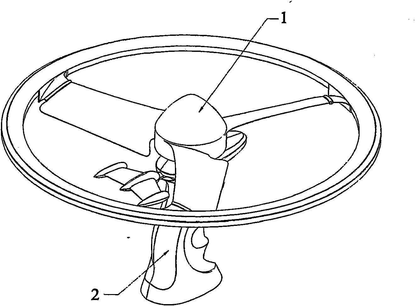
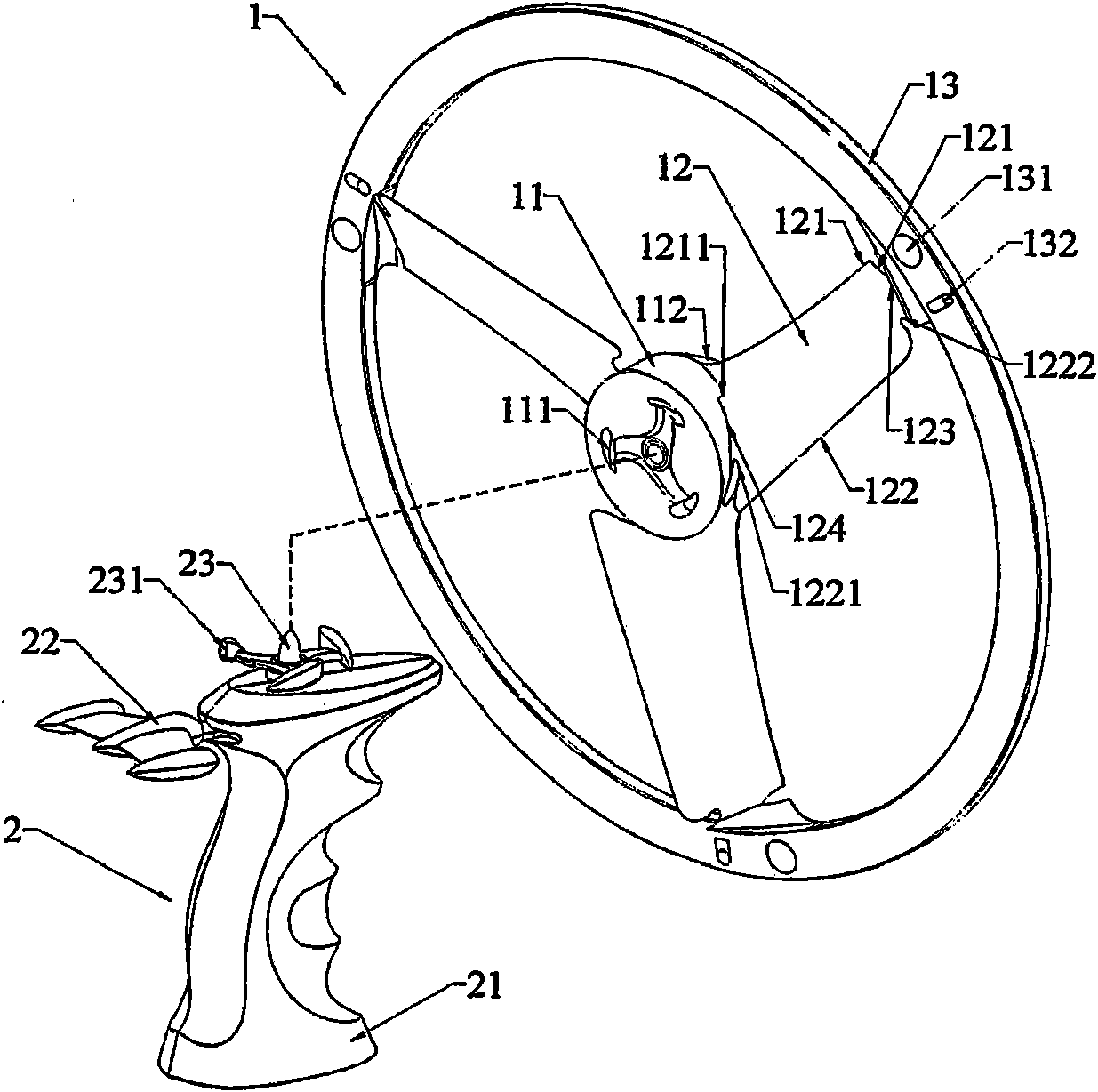
[0033] figure 1 A boomerang 1 with a handheld launcher 2 is shown in a preferred embodiment of the invention. The handheld launcher 2 has a detachable upper part mounted on the central part of the boomerang 1 and is able to transmit a rotational movement to the boomerang 1 . Since the handheld transmitter 2 is not improved, the description of the handheld transmitter 2 is omitted.

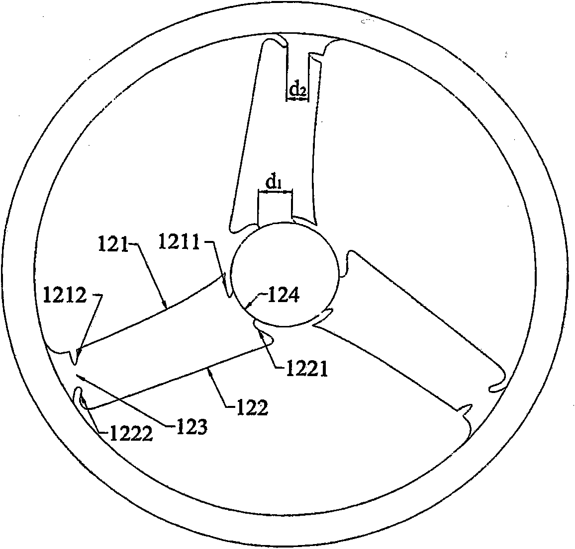
[0034] The boomerang 1 includes blades 12 extending radially from the central part 11, the number of blades may be two or more, preferably three, and the blades 12 have an initial elevation angle α 0 . The initial elevation angle α 0 The optimal value is from about 10° to about 45°. The central part 11 is a closed part with a circular perimeter, the bottom side of which provides means for attachment to the upper part of the hand-held transmitter 2 (see figure 2 ). The upper part of said central part 11 preferably has an aerodynamic shape, for example figure 1The round pyramid is clearly s...


PUM


Abstract

The invention relates to a boomerang that can automatically change both elevation angle a of blades and curve radius r of blades upon the change of rotary speed of blades (12), wherein blades (12) are made of elastically plastic film preferably selected from a group of polyvinyl chloride, polypropylene, polyethylene terephthalate, polystyrene and high impact polystyrene, the material has a specific weight of from about 0,9g / cm3 to about l,60g / cm3 and as thicknesses of from about 0,1mm to about 1mm; the ratio between rear groove deep and blade width is of from about 1 / 7 to about 6 / 7; the ratio between front groove deep and blade width is of from about 0 to about 3 / 7; the elevation angle a0 is of from about 10 DEG to about 45 DEG; the initial curve radius ro of the blades is longer or equal to 1 / 5 of the radius R of said ring (13); the ratio between the total area of said blades and the area of a circle defined by said ring (13) is of from about 12,5% to about 38%.

Description

technical field [0001] The present invention relates to a circular-shaped boomerang (boomerang) with blades inside, which can fly by firing force and then can fly back to its firing position. More specifically, the present invention relates to a boomerang capable of automatically changing the elevation angle of the blade and the radius of curvature of the blade as the rotational speed of the blade changes, thanks to the special structure of the blade shape and the manufacturing process of the blade. Material. Background technique [0002] There are already many flying toys with rotors that are capable of flying by receiving a rotational motion that rotates the rotor about its center. Such a flying toy has been disclosed in US Patent Application No. US2002098768A1 (published on July 25, 2002, inventor: KUO YIN JYH (TW); YANG HSIN-HAO (TW)). Because the rotor of this toy has blades with fixed elevation angles, when receiving the rotational motion, which usually has very high...

Claims


Application Information

Patent Timeline
Patent Type & Authority Applications(China)
IPC IPC(8): A63H27/127
CPCA63H27/12A63H33/18
Inventor 胡永煌
Owner TOSY ROBOTICS
Why Eureka
Try Eureka