
Double 12-pulse valve bank coordinated-control method for ultra-high voltage direct-current transmission system

A UHV DC, coordinated control technology, applied in the direction of parallel operation of DC power supplies, can solve problems such as unbalanced voltage distribution, trigger angle deviation, etc., and achieve the effect of solving competitive control

Active Publication Date: 2010-08-25
NR ELECTRIC CO LTD +2
View PDF0 Cites 31 Cited by
  • Summary
  • Abstract
  • Description
  • Claims
  • Application Information

AI Technical Summary

Problems solved by technology

[0006] The purpose of the present invention is: according to the characteristics of the ±800kV direct current transmission project, a method for coordinated control of double 12 pulsation valve groups is proposed to solve the problem of high and low pressure series valve group trigger angles caused by factors such as competition control among series valve groups and measurement errors. Problems of deviation and unbalanced voltage distribution

Method used


Image

  • Double 12-pulse valve bank coordinated-control method for ultra-high voltage direct-current transmission system
  • Double 12-pulse valve bank coordinated-control method for ultra-high voltage direct-current transmission system
  • Double 12-pulse valve bank coordinated-control method for ultra-high voltage direct-current transmission system

Examples


Embodiment Construction

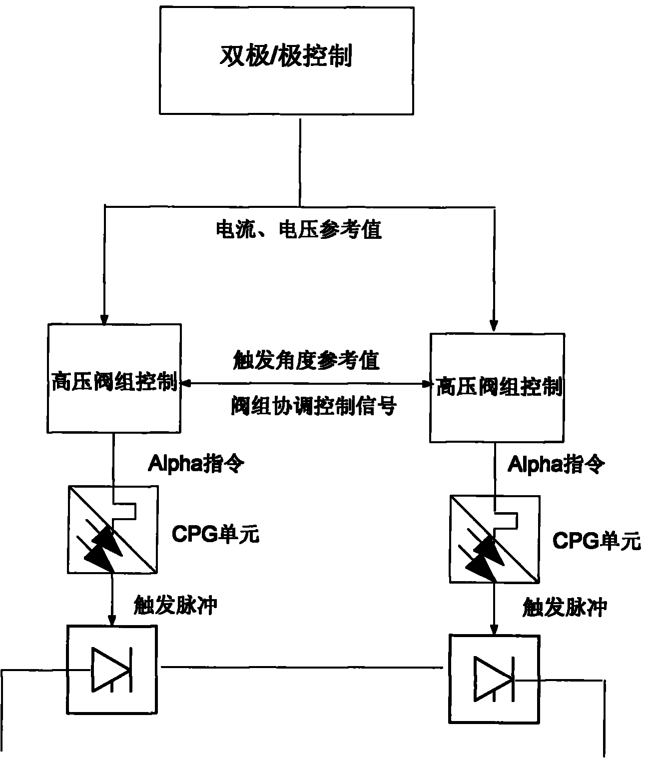
[0018] The present invention will be further described according to the accompanying drawings: In order to realize the coordinated control of each 12-pulse valve group connected in series, a physically independent converter valve control unit is adopted, and the bipolar / polar control layer and the valve group control layer adopt mutual independent device implementation.

[0019] A main computer completes the functions of the bipolar / pole control layer, mainly realizing the calculation and distribution of power / current commands, the coordination of current commands between stations, the switching control of reactive power equipment in stations, and the DC sequence control of stations and poles.

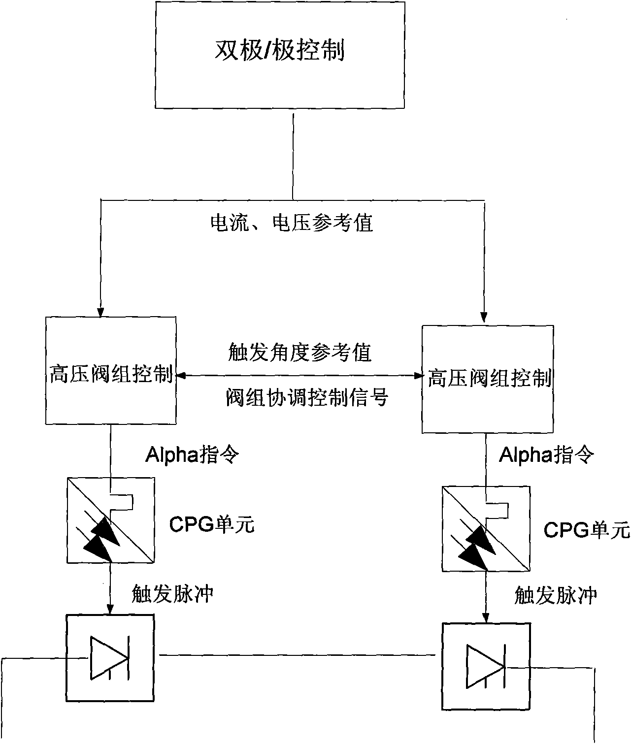
[0020] As shown in Figure 2, bipolar / polar control sends the calculated current and voltage commands to the valve group control host computer at the next level. The valve group control main computer is used for valve group trigger control. The main control functions are: valve group t...


PUM


Abstract

The invention relates to a double 12-pulse valve bank coordinated-control method for an ultra-high voltage direct-current transmission system. The method is realized in a way that: two valve banks at each pole are connected in series, one ends are connected with each other, and the other ends are respectively connected to an polar high voltage bus and a polar neutral bus; the pole control system is divided into a dipole\pole control layer and a valve bank control layer, the valve bank control layer realizes trigger control on the high-voltage valve bank and the low-voltage valve bank, each valve bank control only collects the respective 12-pulse valve bank conversion flow bus voltage as the synchronous voltage of the trigger pulse, the trigger angle of the two 12-pulse valve banks in series can be adjusted to maintain the direct-current current and the direct current voltage, and the trigger angle between the valve banks in series can be coordinated and controlled to realize balanced operation of the valve banks in series; and the dipole\pole control layer generates a current command and simultaneously transmits the current command to high voltage and low voltage, i.e. master-slave valve bank control. The invention solves the problems of trigger angle deviation of high-voltage valve bank and low-voltage bank in series, and unbalanced voltage distribution caused by competitive control between valve banks in series, measuring errors and other factors.

Description

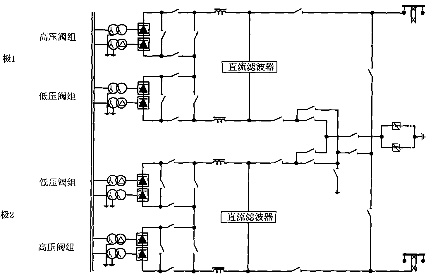
technical field [0001] The invention relates to a coordinated control method of double 12 pulsation valve groups in an extra-high voltage direct current transmission system and control system equipment using the method. Background technique [0002] The primary main wiring of the ±800kV UHV DC system is shown in Figure 1. It adopts the main wiring form of two 12-pulse valve groups in series for each pole, and the voltage of each valve group is 400kV. One end of the two valve groups is connected, and the other end is respectively connected to the extremely high pressure bus and the extremely neutral bus, which can be called the high pressure valve group and the low pressure valve group respectively. In actual operation, the two valve groups can be operated at the same time, or only the high-pressure valve group or the low-pressure valve group can be operated according to the needs. [0003] Each pole in a converter station is equipped with two sets of redundant pole control ...

Claims


Application Information

Patent Timeline
Patent Type & Authority Applications(China)
IPC IPC(8): H02J1/10
Inventor 胡铭邵震霞王振曦
Owner NR ELECTRIC CO LTD
Learn More