
Full-automatic high speed bottle unscrambler

A fully automatic bottle unscrambler technology, applied in the field of bottle unscramblers, can solve the problems of large space occupation, slow bottle unscrambling speed, single shape and size of bottles, etc., and achieves the effects of strong applicability, easy maintenance, and simple use

Active Publication Date: 2010-08-25
黄炎俊
View PDF2 Cites 52 Cited by
  • Summary
  • Abstract
  • Description
  • Claims
  • Application Information

AI Technical Summary

Problems solved by technology

Firstly, it must have a bottle conveying mechanism, and the bottles can only be unscrambled after being arranged and transported to the bottle unscrambler, which increases the cost and structural complexity of the bottle unscrambler; secondly, the mechanism of the bottle unscrambler is semicircular The diameter of the groove or the U-shaped groove is larger than the diameter of the bottle mouth and less than the diameter of the bottom of the bottle, so it is not suitable for unscrambling the wide-mouth and short-necked bottles; three, the bottle-inverting block and the bottle-inverting lever are a fixed structure, The unscrambling effect cannot be realized for bottles with different bottlenecks; fourth, the mechanism of the unscrambling plate is a fixed dial and chassis structure, which cannot be unscrambled for bottles of different sizes, and the dial is made of a fixed semicircular Groove or U-shaped groove, not suitable for unscrambling bottles with different diameters
[0007] To sum up, the existing automatic bottle unscramblers generally have defects such as large space occupation, single shape and size, unstable bottle unscrambling process, and slow bottle unscrambling speed.

Method used


Image

  • Full-automatic high speed bottle unscrambler
  • Full-automatic high speed bottle unscrambler
  • Full-automatic high speed bottle unscrambler

Examples


Embodiment Construction

[0052] In order to further explain the technical means and effects that the present invention takes to achieve the intended purpose of the invention, below in conjunction with the accompanying drawings and preferred embodiments, the specific implementation, steps, features and details of the high-speed automatic bottle unscrambler proposed according to the present invention will be described below. Its effect is described in detail below.

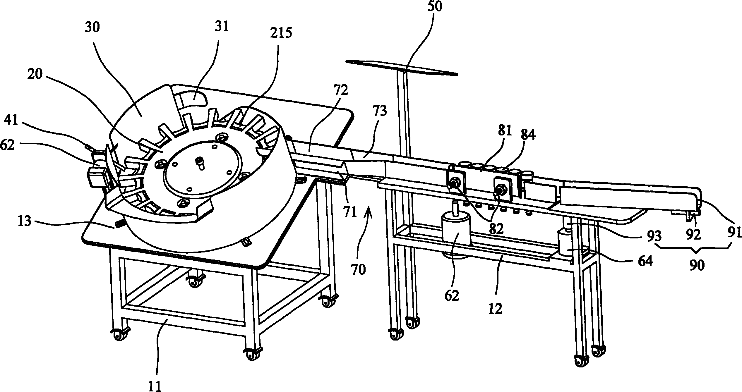
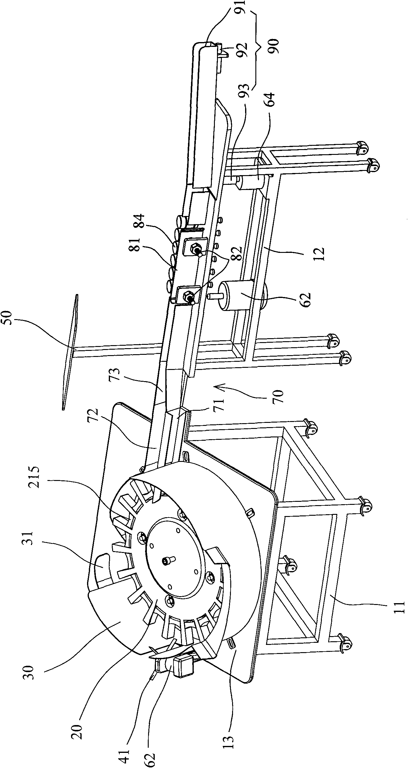
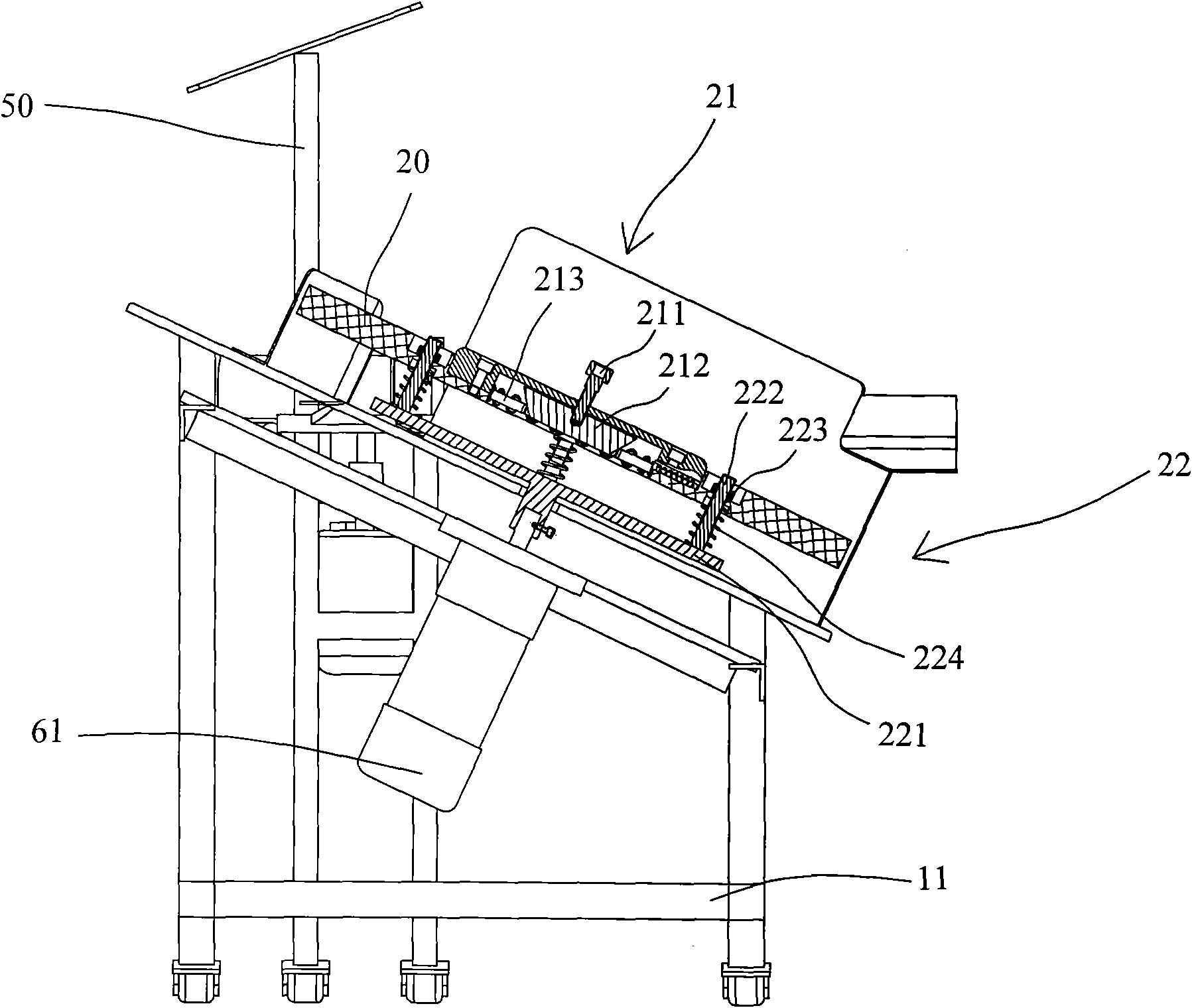
[0053] Please refer to Fig. 1, which is a three-dimensional structural schematic view of the high-speed automatic bottle unscrambler of the present invention. The bottle unscrambler comprises: a frame 10, a chuck 20 positioned on the frame 10, a bottle protection plate 30 arranged on the periphery of the chuck 20, a bottle turning mechanism 40 for turning the bottle mouth downwards to the bottle mouth upwards , a console 50 for man-machine interface operation, a driving device 60, a conveying mechanism 70, a cleaning mechanism 80 and a dete...


PUM


Abstract

The invention relates to a full-automatic high speed bottle unscrambler, comprising a stand, a clamping chuck, a bottle-turning mechanism, a bottle-turning strip, a bottle-standing plate, a control desk, a driving device and a conveying mechanism, wherein the stand is provided with a declining faceplate; the clamping chuck is installed on the declining faceplate and is provided with a radial regulating mechanism and a bottle height regulating mechanism, and a bottle-protecting plate is installed at the periphery of the clamping chuck; the bottle-turning mechanism is used for guiding bottles which do not enter the clamping chuck in accordance with a normal order into a bayonet of the clamping chuck and includes a screening stirring strip installed on the faceplate and located at the opening of one end of the bottle-protecting plate; the bottle-turning strip is installed on the faceplate and used for correctly turning the bottles, the bottle-standing plate is installed at the back of the bottle-turning strip and used for standing the bottle bodies; the control desk is used for man-machine interface operation; the driving device is installed on the stand; and the conveying mechanism is used for guiding out the bottles which are cleaned by the clamping chuck. The full-automatic high speed bottle unscrambler has simple structure and can regulate the arrangement of the bottles with different diameters and lengths of bottle bodies, different diameters of bottle jacks and different sizes and heights of bottle necks within a certain range.

Description

technical field [0001] The invention relates to a bottle unscrambler, in particular to a high-speed automatic bottle unscrambler for medium and small plastic bottles in medicine bottle packaging. Background technique [0002] The function of the bottle unscrambler is to arrange the unscrambled bottles to be processed, arrange them on the conveyor belt in an orderly and directional manner, and transfer them to the next process smoothly. In the automatic production line of injection blown hollow products, if there is no bottle unscrambler to match it, if manual bottle picking is used, the production scene will be quite busy and the work efficiency will be relatively low. [0003] The main features and importance of the bottle unscrambler are roughly three points: 1) Improve the working efficiency of the packaging production line and reduce the labor intensity of workers; 2) Ensure that the packaging containers such as food and medicine can be aseptic and hygienic so as to meet...

Claims


Application Information

Patent Timeline
Patent Type & Authority Applications(China)
IPC IPC(8): B65G47/24B65B43/42B65B55/24B65B57/02B08B9/08
Inventor 黄炎俊
Owner 黄炎俊
Learn More