
Sintering machine partial fume denitrating system and method thereof

A sintering machine and flue gas technology, applied in separation methods, chemical instruments and methods, dispersed particle separation, etc., can solve problems such as difficult to achieve expected results, unsuitable for sintering flue gas, low NOx concentration, etc., and achieve total NOx emissions Reduction, NOx removal operation cost reduction, construction investment reduction effect

Inactive Publication Date: 2012-03-14
BAOSTEEL ENG & TECH GRP
View PDF1 Cites 2 Cited by
  • Summary
  • Abstract
  • Description
  • Claims
  • Application Information

AI Technical Summary

Problems solved by technology

This technology is to collect the flue gas at the tail of the sintering machine separately and directly send it to the denitrification device for denitration treatment. The temperature of the flue gas at this part is a suitable temperature for denitrification; however, the concentration of NOx in the flue gas is low, and the selective catalytic Reduction method (SCR) denitrification technology is not suitable for sintering flue gas without dust removal, so it is difficult to achieve the expected effect

Method used


Image

  • Sintering machine partial fume denitrating system and method thereof
  • Sintering machine partial fume denitrating system and method thereof
  • Sintering machine partial fume denitrating system and method thereof

Examples


Embodiment Construction

[0038] The present invention will be described in detail below in conjunction with the accompanying drawings and embodiments.

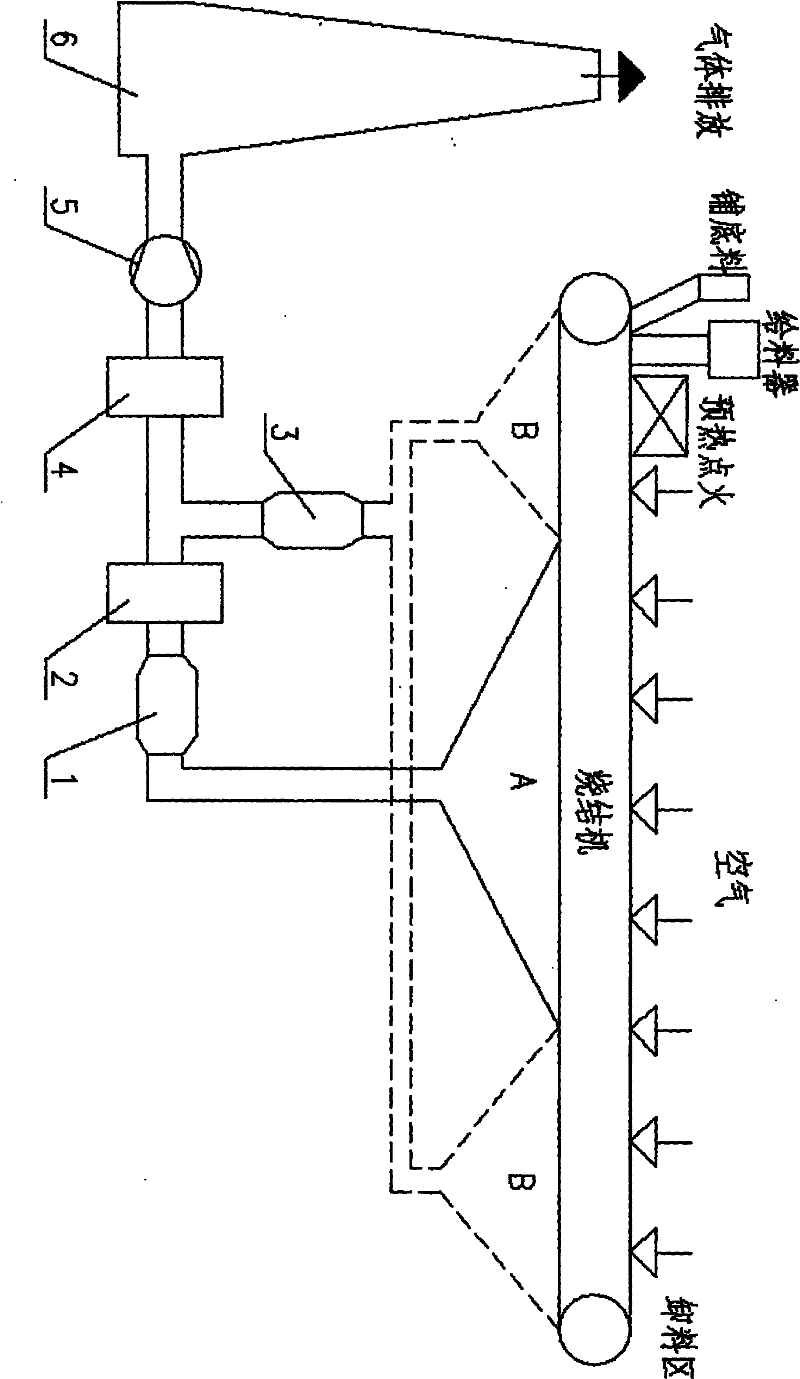
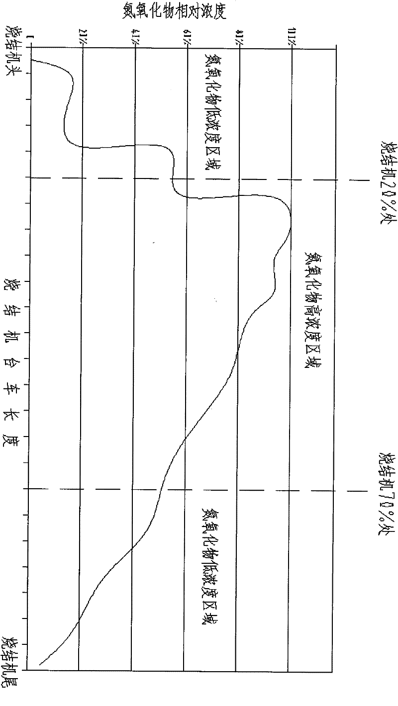
[0039] see figure 1 , a partial flue gas denitrification system of a sintering machine of the present invention divides all the exhaust boxes at the lower part of the sintering machine trolley into high-concentration areas and low-concentration areas according to the concentration of nitrogen oxides. 2. Dust collector 3, desulfurization device 4, fan 5, chimney 6, wind box A in the high concentration area of ​​nitrogen oxides and wind box B in the low concentration area of ​​nitrogen oxides.

[0040] The denitrification and dust collector 1 is connected to the air box A in the area with high concentration of nitrogen oxides, and collects the flue gas in the air box in this area.

[0041] The dust collector 3 is connected to the wind box B in the low concentration area of ​​nitrogen oxides to collect the flue gas in this area.

[0042] The desulfuriz...


PUM


Abstract

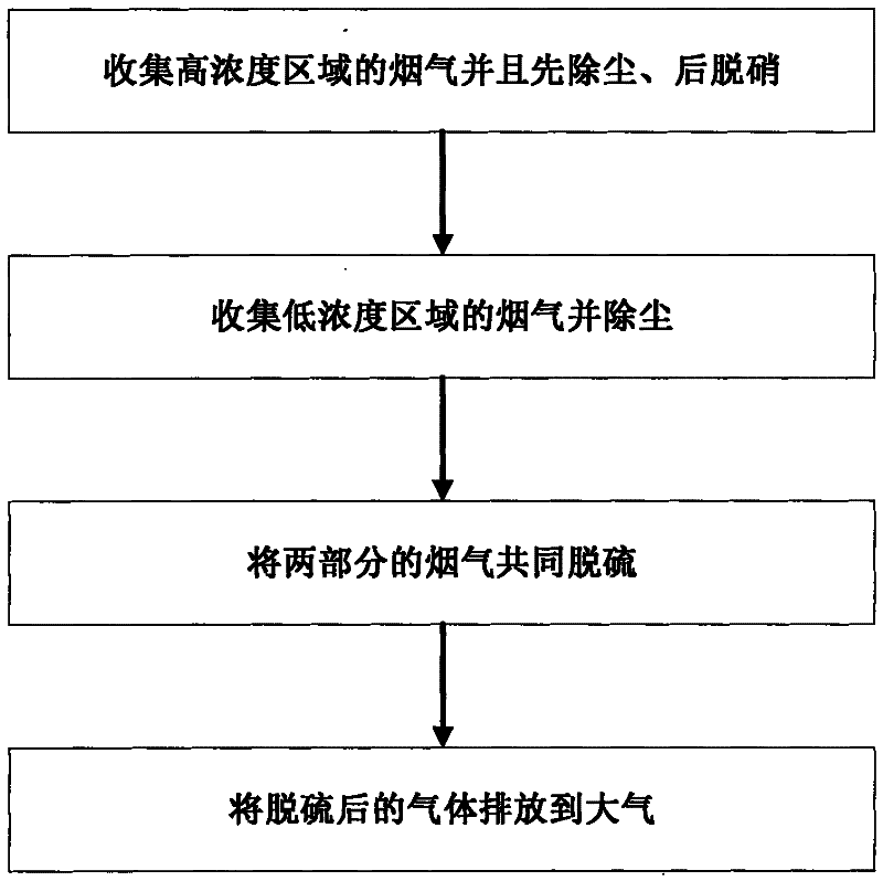
The invention relates to a sintering machine partial fume denitrating system and a method thereof. The denitrating system comprises an air box A in the high-concentration nitrogen oxide zone, an air box B in the low-concentration nitrogen oxide zone, a denitrating dust catcher, a denitrating device, a dust catcher, a desulfurizing device, a blower fan and a chimney, wherein the denitrating dust catcher is connected with the air box A to collect fumes in the air box in the zone, and the denitrating dust catcher is orderly connected with the denitrating device and the desulfurizing device and introduces the dedusted and denitrated fumes to the desulfurizing device; the dust catcher is connected with the air box B to collect fumes in the zone, and the dust catcher is connected with the desulfurizing device and introduces the dedusted fumes to the desulfurizing device; and the desulfurizing device is connected with the chimney, and discharges the desulfurized fumes to the atmosphere. The method comprises the following steps: collecting the fumes in the high-concentration zone, dedusting, and then denitrating; collecting the fumes in the low-concentration zone and dedusting; desulfurizing the two parts of fumes together; and discharging the desulfurized gas to the atmosphere. By using the technical scheme, the total emission load of NOx is decreased by 60% or so, thereby reducing the construction investment and the operation cost.

Description

technical field [0001] The invention relates to a sintering machine flue gas nitrogen oxide emission reduction technology in the field of iron and steel metallurgy, in particular to a partial flue gas denitrification system and method for sintering machine pre-iron system in the iron and steel industry. Background technique [0002] Sintering production is an important process unit of modern iron and steel production. A large amount of air pollutants will be produced during the production process, and it is the largest polluter in iron and steel complexes; the NOx emitted by the sintering unit generally accounts for about 60% of the total emissions of the whole plant (excluding self-provided power plants), it is the largest NOx polluter in iron and steel complexes. At present, the country has no clear requirements for sintering denitrification; but at the end of the "Eleventh Five-Year Plan", the country has put "nitrogen oxide emission reduction" on the agenda (mainly for t...

Claims


Application Information

Patent Timeline
Patent Type & Authority Patents(China)
IPC IPC(8): B01D53/86B01D53/56
Inventor 张传秀吴伟刘平刘旭华王彦宁冀蓉王永忠
Owner BAOSTEEL ENG & TECH GRP
Learn More