
Method for manufacturing insulation layer of touch panel

A manufacturing method and touch panel technology, which are applied in the photoengraving process of pattern surface, semiconductor/solid-state device manufacturing, original parts for opto-mechanical processing, etc., can solve the problems of increased cost, complicated steps, dangerous processing process, etc. , to achieve the effect of improving yield, reducing costs, and reducing processing procedures

Inactive Publication Date: 2010-08-18
百倍光电股份有限公司
View PDF0 Cites 7 Cited by
  • Summary
  • Abstract
  • Description
  • Claims
  • Application Information

AI Technical Summary

Problems solved by technology

[0003] Although the steps mentioned above can complete the production of the insulating layer of the touch panel, because the silicon dioxide insulating layer is coated, it must also go through cleaning, photoresist coating, development and BOE etching or dry etching, etc. steps, so that the formation speed of the silicon dioxide insulating layer is relatively slow, and when BOE etching or dry etching is performed in this step, not only will the processing process be more dangerous, but also have adverse effects on the environment, resulting in the existing touch panel When making the insulating layer, the relevant steps are relatively complicated, resulting in a waste of man-hours and processes, and at the same time increasing the cost of manufacturing; therefore, the above-mentioned existing method of manufacturing the insulating layer of the touch panel cannot meet the needs of actual use

Method used


Image

  • Method for manufacturing insulation layer of touch panel
  • Method for manufacturing insulation layer of touch panel
  • Method for manufacturing insulation layer of touch panel

Examples


Embodiment Construction

[0034] The above and other technical features and advantages of the present invention will be described in more detail below in conjunction with the accompanying drawings.

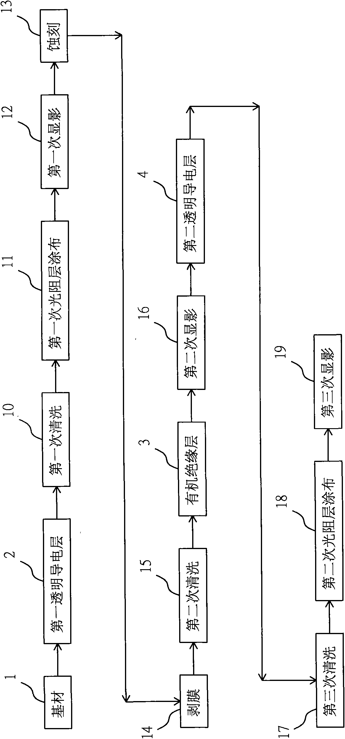
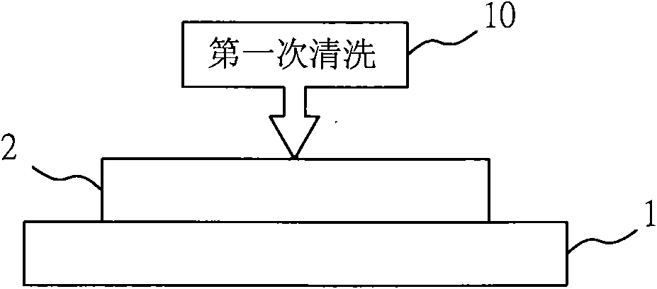
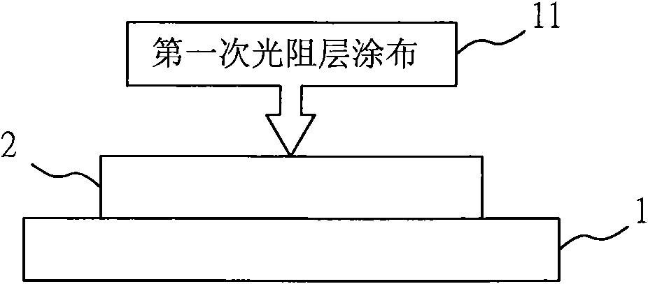
[0035] Figure 1-Figure 10 Shown are the schematic flow diagram of the present invention, the schematic diagrams of steps 1 to 8 of the present invention, and the schematic diagrams of another embodiment of the present invention. As shown in the figure: a method for manufacturing an insulating layer of a touch panel provided by the present invention can achieve the effects of reducing processing procedures, improving yield and reducing costs when manufacturing an insulating layer of a touch panel, which at least includes the following steps :

[0036] Step 1: Take a substrate 1 that can be a glass substrate or polyethylene terephthalate (PET), coat the first transparent conductive layer 2 on the substrate 1, and perform the first Second cleaning 10, wherein the first transparent conductive layer 2 is sel...


PUM


Abstract

The invention relates to a method for manufacturing an insulation layer of a touch panel, which comprises the following steps of: plating a first transparent conducting layer on a substrate, cleaning for the first time, then coating a first photoresist layer to generate a conductive circuit graphic, developing for the first time, then etching and decoating the photoresist layer, cleaning for the second time to expose the conductive circuit, coating an organic insulation layer on the first transparent conducting layer, developing for the second time, then plating a second transparent conducting layer on the organic insulation layer, cleaning for the third time, coating a second photoresist layer on the second transparent conducting layer to generate another required conductive circuit graphic, and finally carrying out the third development on the conductive circuit graphic on the photoresist layer with a developer, therefore, the invention achieves the effects of reducing processing procedures and lowering cost when being used for manufacturing the insulation layer of the touch panel.

Description

technical field [0001] The invention relates to a method for manufacturing an insulating layer of a touch panel, in particular to a method for manufacturing an insulating layer of a touch panel that can reduce processing procedures, improve product quality and reduce costs. Background technique [0002] At present, when making the insulating layer of the general existing touch panel, at least need to carry out: glass substrate→indium tin oxide coating→cleaning→photoresist coating→developing→etching→stripping→silicon dioxide insulating layer Coating → cleaning → photoresist coating → development → BOE etching or dry etching → stripping → indium tin oxide coating → cleaning → photoresist coating → development → etching → stripping and other steps, thus completed Fabrication of the insulating layer of the touch panel, wherein the BOE etching refers to Buffered Oxide Etch (BOE) buffered oxide etching. [0003] Although the steps mentioned above can complete the production of th...

Claims


Application Information

Patent Timeline
Patent Type & Authority Applications(China)
IPC IPC(8): H01L21/768H01L21/02G03F1/16
Inventor 邝东元陈仲豪
Owner 百倍光电股份有限公司
Learn More