Method and device for continuous up-casting of copper-clad steel

A copper cladding and continuous casting technology, applied in the field of composite material manufacturing, can solve the problems of poor bonding force, difficult quality assurance, long process flow, etc.

Inactive Publication Date: 2010-08-18
秦志春 +1
View PDF5 Cites 9 Cited by
  • Summary
  • Abstract
  • Description
  • Claims
  • Application Information

AI Technical Summary

Problems solved by technology

Although these methods can produce copper-clad steel, they all have obvious disadvantages: for example, the casting hot pressing method has a long process flow, and the material utilization rate is low, and the quality is difficult to guarantee; the copper strip crimping method costs 15% more. %-20%; the electroplating method causes serious pollution due to the use of cyanide, and the surface electroplating solution is not easy to clean, which makes the copper black and finally forms holes; both the welded pipe coating method and the casing coating method are difficult to obtain due to poor bonding force Satisfied with the effect
To overcome this shortcoming, it is necessary to replace the mold in time, which seriously affects the production capacity.
[0007] (3) Since the steel core rod is immersed in copper water for 6-8 seconds, when the surface temperature of the steel core in high-temperature copper water is greater than 760°C, some phosphorus ions will be released into the copper water, polluting the copper water, resulting in The electrical conductivity drops sharply, which destroys the electrical properties of copper-clad steel
[0008] To sum up, it is not suitable to produce copper-clad steel products with high tensile strength, high conductivity, corrosion resistance and small cross-section according to the above method, and the electric power construction urgently needs this product

Method used


Image

  • Method and device for continuous up-casting of copper-clad steel
  • Method and device for continuous up-casting of copper-clad steel
  • Method and device for continuous up-casting of copper-clad steel

Examples


Embodiment Construction

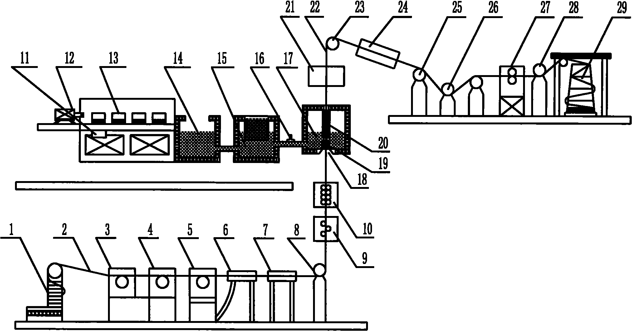
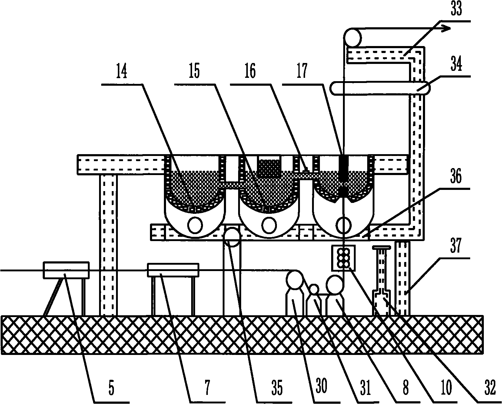
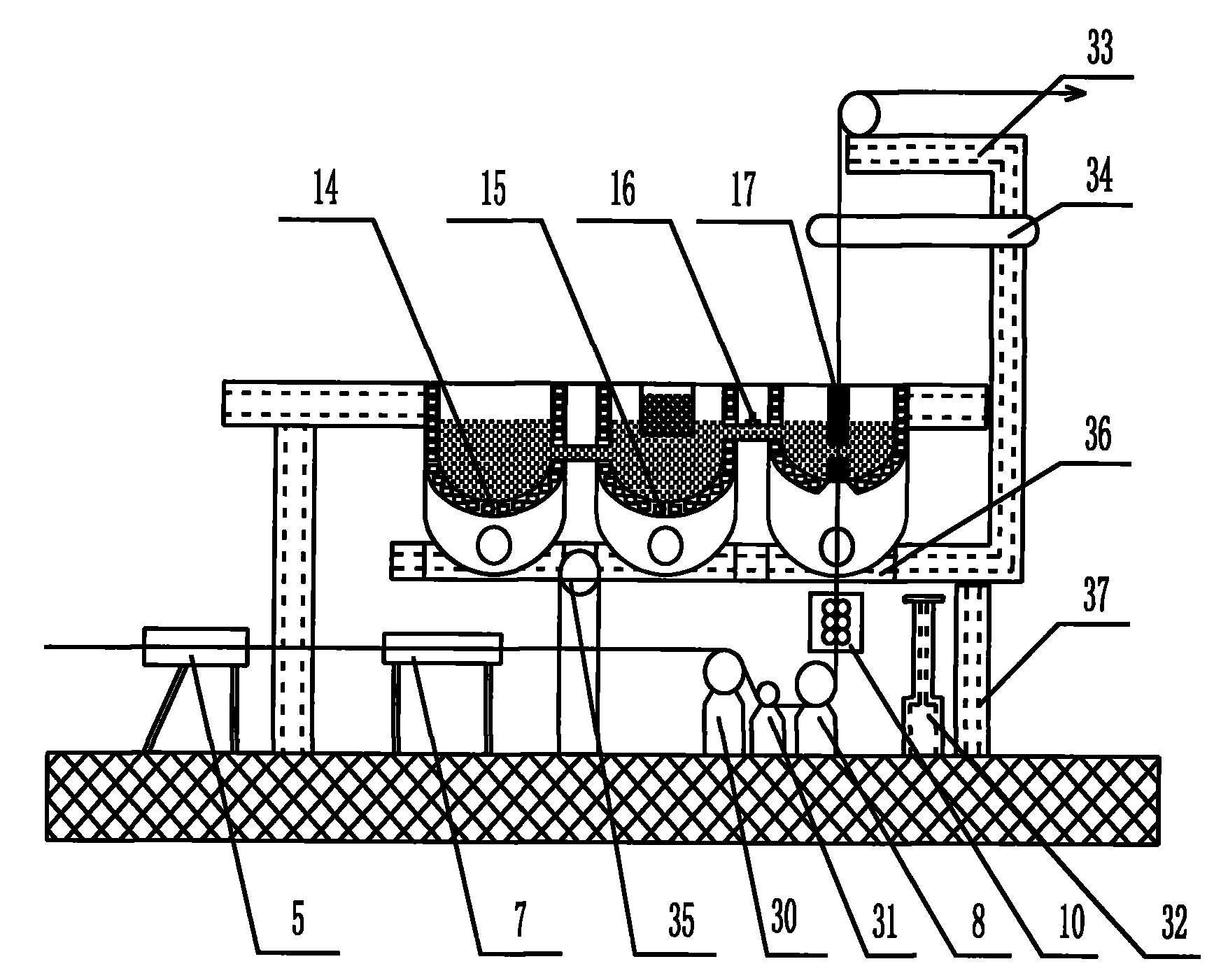
[0025] Such as figure 1 and figure 2 , including 1 pay-off machine, 2 steel core wire, 3 peeling machine, 4 wire drawing machine, 5 polishing machine, 6 ultrasonic cleaning machine, 7 preheating and gas protection device, 8 lower guide wheels 1 , 9 Straightening machine, 10 Compacting machine, 11 Copper plate before preheating, 12 Copper plate feeding machine, 13 Copper plate after preheating, 14 Melting furnace, 15 Holding furnace, 16 Continuous casting furnace valve, 17 Continuous casting furnace, 18 Continuous casting furnace Furnace inlet, 19 lower graphite mold, 20 upper graphite mold crystallizer, 21 water cooling device, 22 copper-clad steel wire, 23 upper guide wheel 1 , 24 duct and gas cooling device, 25 upper guide wheel 2 , 26 upper guide wheels 3 , 27 hot rolling rolls, 28 upper guide wheels 4 , 29, take-up machine, 30 lower guide wheels 2 , 31 lower guide wheels 3 , 32 furnace body lifting devices, 33 rocker arm seats, 34 lifting device universal rocker arm...


PUM

PropertyMeasurementUnit
preheating temperatureaaaaaaaaaa

Abstract

The invention discloses a method and a device for the continuous up-casting of copper-clad steel. The method comprises the key points that: a preheated steel core wire enters from the bottom of a continuous casting furnace, and then is vertically dragged out of the upper part of the continuous casting furnace after continuous casting and cladding in melted copper in the furnace in sequence. The preheating temperature of the steel core wire is between 600 and 700 DEG C; the temperature of the melted copper is controlled to between 1,150 and 1,110 DEG C; the cladding distance of the steel core wire in copper liquid is controlled to between 8 and 17cm; and the speed at which the copper-clad steel core wire after the continuous casting is extracted from the furnace is between 100 and 120m/min. Meanwhile, the device makes the continuous casting furnace keep constant temperature and ensures the quality of products because a melting furnace, a heat preserving furnace and the continuous casting furnace are connected with one another; and moreover, because the device is provided with a furnace body lifting device, the device can conveniently transfer the melted copper in the continuous casting furnace so as to facilitate maintenance.

Description

technical field [0001] The invention relates to a production method and device for a power overhead wire with good concentricity, high conductivity, high tensile strength and corrosion resistance, especially a method and device for coating copper on a steel core wire, belonging to composite materials manufacturing field. Background technique [0002] Copper clad steel wire (abbreviated as CCS) is a kind of multi-metal composite material with high-quality carbon steel as the core and copper as the surface cladding layer, which is processed into a whole. Tensile strength, and good electrical conductivity and corrosion resistance of copper. With the continuous development of social economy, the load of the power grid increases and the continuous construction of power points, the system capacity is also increasing. Correspondingly, the short-circuit current of each substation is also increasing. For high-voltage transmission lines, the thermal stability of the ground wires in ...

Claims


Application Information

Patent Timeline
Patent Type & Authority Applications(China)
IPC IPC(8): B22D11/04B22D19/08
Inventor 秦志春黄国华
Owner 秦志春
Why Eureka
Try Eureka