
Bearing device for wheel

A bearing device and wheel technology, applied in the directions of bearings, axles, wheels, etc., can solve the problems of poor component management, large number of components, and poor workability, and achieve the effects of stabilizing torque, improving strength, and inhibiting looseness

Active Publication Date: 2010-08-11
NTN CORP
View PDF1 Cites 2 Cited by
  • Summary
  • Abstract
  • Description
  • Claims
  • Application Information

AI Technical Summary

Problems solved by technology

Therefore, there is a screw fastening operation during assembly, and workability is poor, and the number of parts is large, and parts management is also poor.

Method used


Image

  • Bearing device for wheel
  • Bearing device for wheel
  • Bearing device for wheel

Examples


Embodiment 1

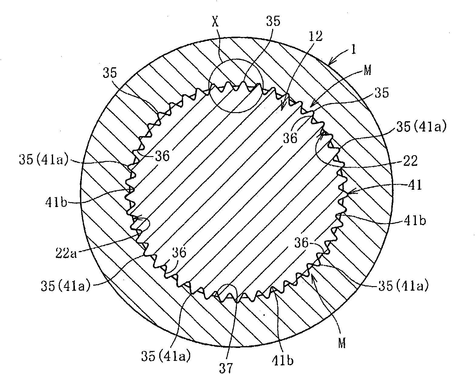
[0226] A male spline with a modulus of 0.48 and a number of teeth of 58 is formed on the shaft portion 12, and the press-fit load is measured when the cross angle θ1 is changed, where the cross angle θ1 is defined as the distance between the end surface 35a and the axis of the convex portion 35 at the start of press-fit. angle formed. In addition, the formability of the concave-convex fitting structure M when the intersection angle θ1 was changed was also evaluated. Figure 37 The measurement results of press-fit load are shown in , Figure 41 The evaluation results of formability are shown.

[0227] Depend on Figure 37 It can be seen that when the intersection angle θ is smaller than 50°, the press-fitting load increases. In addition, when the intersection angle θ is larger than 110°, the spline end surface is likely to be chipped, and when the chip is formed, the formability of the concave-convex fitting structure M deteriorates sharply, and the press-fitting load increa...

Embodiment 2

[0230] A male spline 41 having a modulus of 0.48 and a number of teeth of 59 was formed on the shaft portion 12, and Δd / 2h was varied to measure the press-fit load. Furthermore, a torsional strength test was performed on each of the concave-convex fitting structures, and the formability of the concave-convex fitting structure M was evaluated. Figure 38 The measurement results of press-fit load are shown in , Figure 39 shows the evaluation results of the torsional strength test, Figure 42 The evaluation results of the formability of the concave-convex fitting structure are shown in .

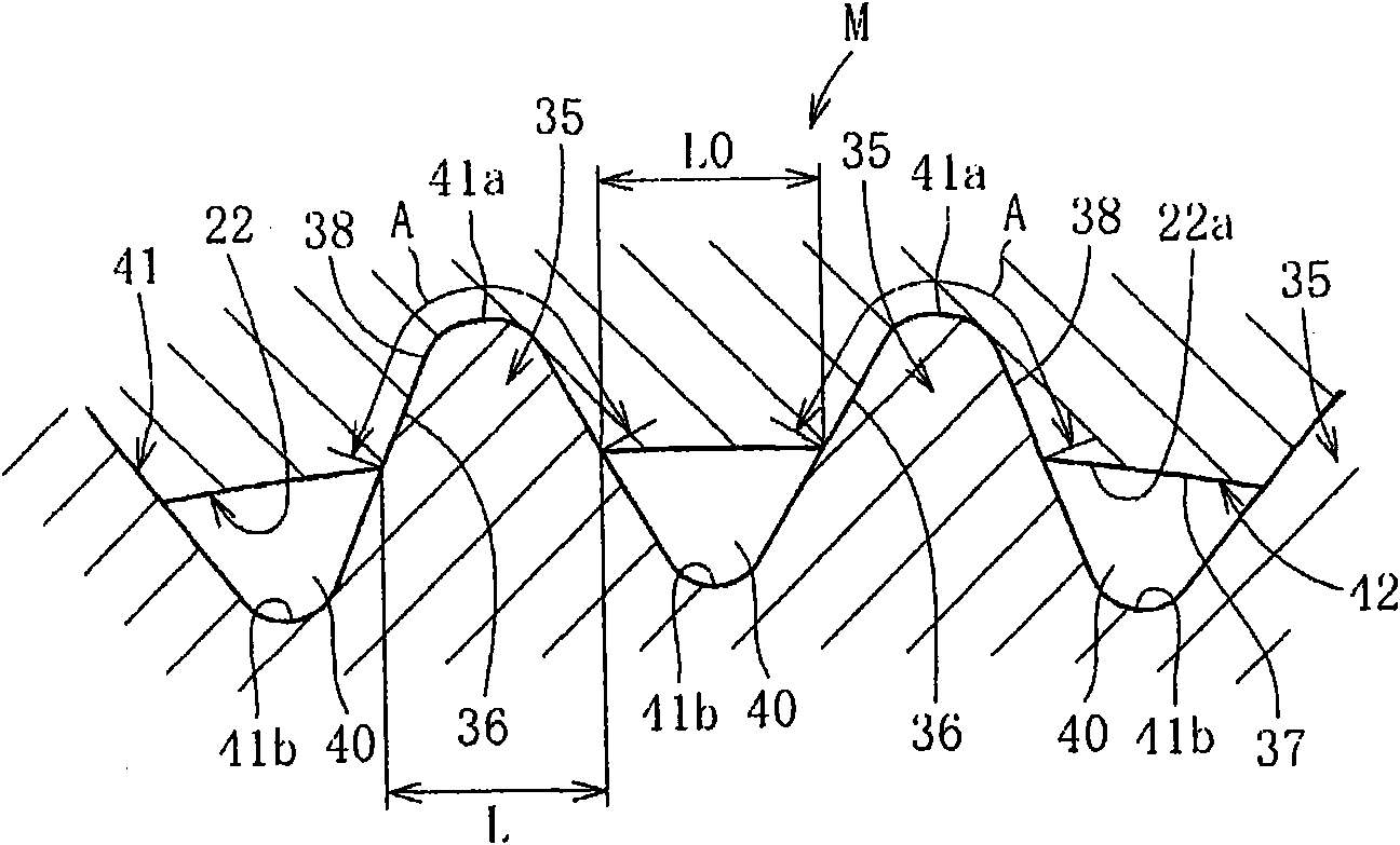
[0231] Depend on Figure 38 with Figure 39 It can be seen that when Δd / 2h exceeds 0.86, the press-fitting load increases rapidly and the torsional strength decreases. In addition, when Δd / 2h is 0.3 or less, the torsional strength decreases. Therefore, it is preferable that 0.3 Figure 42 It can be seen that the formability of the concave-convex fitting structure M is good when Δd / 2h is in...


PUM

PropertyMeasurementUnit
Radial lengthaaaaaaaaaa

Abstract

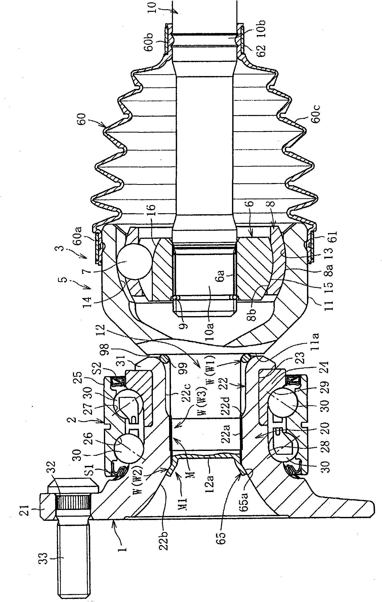
A bearing device for a wheel, in which circumferential play is suppressed and in which a hub ring and an outer ring of a constant velocity universal joint can be firmly and easily joined to each other. An axially extending projection (35) is formed on a shaft section (12) of the joint outer ring (5), and the shaft section (12) is press-fitted into a hole (22) of the hub ring (1). By this press-fitting, a recess (36) closely fitting on the projection (35) is formed in the inner diameter surface of the hub ring (1) to form a recess / projection fit structure (M) in which the entire regions of those portions of the projection (35) and the recess (36) at which they are fitted to each other are in close contact with each other. The bearing device satisfies the relationship of 0.3 < Deltad / 2h < 0.86, where Deltad is the press-fit interference of the projection (35) relative to the hub ring (1) and h is the height of the projection.

Description

technical field [0001] The present invention relates to a wheel bearing device for rotatably supporting a wheel with respect to a vehicle body in a vehicle such as an automobile. Background technique [0002] In wheel bearing devices, the first-generation structure, which is called the combination of multiple rows of rolling bearings, has evolved to the second-generation structure, in which the body mounting flange is integrally provided on the outer member, and has been further developed. The third generation of rolling bearings in which one of the two inner raceway surfaces is formed on the outer circumference of the hub ring, and further, a multi-row rolling bearing in which one of the two inner raceway surfaces is formed on the outer circumference of the hub ring and the other is developed The fourth-generation wheel bearing device is formed on the outer circumference of the outer joint member of the constant velocity universal joint. [0003] For example, Patent Docume...

Claims


Application Information

Patent Timeline
IPC IPC(8): F16C35/063B60B35/14B60B35/18F16C33/58F16D3/20
CPCF16D2001/103F16C35/0635F16C19/186B60B27/0094F16D1/072B21D53/10B60B27/0005F16C2326/02B60B27/0078B60B27/0084F16D1/108B60B27/0026B60B27/0042F16C19/184F16D2003/22326Y10T29/49535B60B35/14B60B35/18F16C33/58F16C35/063
Inventor 中川亮浅野祐一小泽仁博黑田正幸
Owner NTN CORP
Learn More