Differential frequency circuit of plesio-digital signal and differential frequency method thereof

A digital signal and circuit technology, applied in the field of signal processing, can solve the problems of output signal duty cycle not 50%, poor thermal stability, non-unique difference frequency output period, etc., so as to solve the problem of resistance-capacitance matching and improve thermal stability. , to achieve a simple effect

Inactive Publication Date: 2010-08-11
TIANJIN AGRICULTURE COLLEGE
View PDF2 Cites 4 Cited by
  • Summary
  • Abstract
  • Description
  • Claims
  • Application Information

AI Technical Summary

Problems solved by technology

The traditional frequency measurement methods mainly include: (1) counting method: this method generally uses seconds as the gate to count the frequency to be measured, and its existing problems are: the counting error of ±1, the resolution of small frequency increments is low, Although the requirement of resolution can be met by extending the gate time, the real-time performance of the sensor is reduced; (2) Periodic method: This method uses one or more periods of the frequency to be measured as a gate and counts a known frequency, The existing problem is: the counting error of ±1, to improve the resolution of small frequency increments, the counting speed of the measurement circuit should be very high, which is difficult to meet in practical applications, although more cycles can be used as gates to meet the resolution requirements, but also reduces the real-time performance of the sensor
[0003] 1. Chinese patent (patent number: 200610122282.8, patent name: logic mixing circuit and logic mixing method) discloses a logic mixing circuit and a mixing method, which uses the signal to be tested and the reference signal for mixing and filtering And the shaping circuit outputs the difference frequency signal. The problem is that because a mixer is used to mix the reference signal and the signal to be tested, the output signal of the mixer contains many harmonics, so it is very difficult to put forward the filter circuit. High requirements, when the difference frequency of the two mixing signals is not much smaller than their sum frequency, the filter circuit must be multi-order or high-order, the circuit is complex, and the thermal stability is poor
The existing problems are: (1) The duty cycle of the output signal is not 50%; (2) Even if the frequency of the two quasi-digital signals is fixed, the period of the difference frequency output is not unique, which will bring a large frequency measurement error
[0005] To sum up, the existing difference frequency circuit and its implementation method still have problems such as circuit complexity, poor thermal stability, and large measurement error.

Method used


Image

  • Differential frequency circuit of plesio-digital signal and differential frequency method thereof
  • Differential frequency circuit of plesio-digital signal and differential frequency method thereof
  • Differential frequency circuit of plesio-digital signal and differential frequency method thereof

Examples


Embodiment Construction

[0035] Embodiments of the present invention will be described in further detail below in conjunction with the accompanying drawings.

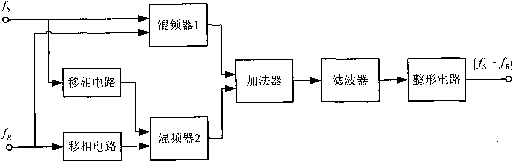
[0036] A difference frequency circuit for quasi-digital signals, such as figure 1 As shown, it is composed of two mixers, two phase shifting circuits, an adder, a filter and a shaping circuit. Bidirectional digital signal f S , f R respectively connected to the two input terminals of the first mixer, and the two quasi-digital signals are mixed by the first mixer; at the same time, the two quasi-digital signals f S , f R Also be connected with respective phase-shifting circuit respectively, by two phase-shifting circuits, carry out the phase-shifting processing of quarter cycle respectively to two quasi-digital signals respectively, the output end of two phase-shifting circuits is connected to the second mixer respectively The two input ends are mixed by the second mixer for the phase-shifted signal. The output ends of the two mixers are re...


PUM


Abstract

The invention relates to a differential frequency circuit of plesio-digital signals and a differential frequency method thereof. The two plesio-digital signals are respectively connected with two input ends of a first mixer of the differential frequency circuit and also respectively connected with two input ends of a second mixer thereof by a phase-shift circuit of the differential frequency circuit. The differential frequency circuit of the plesio-digital signals and the differential frequency method thereof are technically characterized in that: the output ends of the two mixers are respectively connected to the two input ends of an adder; the output ends of the adder are connected with a filter and a shaping circuit in sequence; the differential frequency method conducts frequency-mixing processing on the two plesio-digital signals by the two mixers; the adder conducts analog adding processing for the mixed signals; and after output of the adder is processed by filtering and shaping, the adder outputs square wave signals with duty cycle of being close to 50 percent and uniform cycle. By adopting the adder behind the two mixers, the differential frequency circuit of the plesio-digital signals and the differential frequency method thereof remove parts of harmonic synthesis items which are close to the frequency of differential frequency in output of the mixers, thus providing a foundation for the measurement of high resolution and high accuracy of a plesio-digital signal output type sensor.

Description

technical field [0001] The invention belongs to the field of signal processing, in particular to a frequency difference circuit of a quasi-digital signal and a frequency difference method thereof. Background technique [0002] The output of the quasi-digital signal output sensor has a certain center frequency. The change of the output frequency is generally 10% of the center frequency within the full scale. How to measure this small frequency increment with high resolution is of great significance. The so-called quasi-digital signal is a square wave signal with a constant amplitude in time and a duty cycle of 50%. The traditional frequency measurement methods mainly include: (1) counting method: this method generally uses seconds as the gate to count the frequency to be measured, and its existing problems are: the counting error of ±1, the resolution of small frequency increments is low, Although the requirement of resolution can be met by extending the gate time, the real-...

Claims


Application Information

Patent Timeline
IPC IPC(8): H03D7/00H03K5/26
Inventor 张伟玉董晋峰赵金才
Owner TIANJIN AGRICULTURE COLLEGE
Why Eureka
Try Eureka