
Suspension rotor equivalent disturbance current compensation control device for bearing-free permanent magnet synchronous motor

A permanent magnet synchronous motor, suspended rotor technology, applied in the direction of single motor speed/torque control, electronic commutation motor control, control system, etc. Influence, rotor mass eccentricity, etc.

Active Publication Date: 2010-08-04
KUNSHAN PANGOLIN ROBOT
View PDF3 Cites 10 Cited by
  • Summary
  • Abstract
  • Description
  • Claims
  • Application Information

AI Technical Summary

Problems solved by technology

[0008] 1. Constant disturbance: The influence of the self-weight of the suspended rotor or working with a constant load has an impact on the dynamic performance of the motor for floating and the steady-state performance of stable suspension;
[0009] 2. Sinusoidal disturbance: The mass imbalance of the motor rotor due to design, processing technology and other reasons. When the motor is running at high speed, the sinusoidal disturbance with the same frequency as the rotational speed is generated due to the imbalance of the rotor mass and acts on the suspension rotor, affecting the stable suspension. performance
[0010] 3. Step disturbance: When the motor is running stably, the rotor radially adds a sudden load, which has an impact on the dynamic and steady-state performance of the motor suspension system
Most of the disturbance observers used in motor control are traditional disturbance observation algorithms. The biggest shortcoming lies in the dependence on the mathematical model of the controlled object, which limits the effect of disturbance observation to a certain extent.
At present, some scholars also apply advanced control algorithms such as adaptive control and wavelet transform to online observation of the key parameters of the controlled object in the disturbance observation algorithm to overcome the dependence of the observer on the mathematical model of the controlled object. However, these advanced control algorithms involve More mathematical knowledge, more complex calculation and implementation, directly lead to difficulties in realizing the disturbance observer
[0013] At present, there is no report on the observation of the disturbance acceleration of the suspended rotor of the alternating pole bearingless permanent magnet synchronous motor and the compensation control of the equivalent disturbance current, even the research on the disturbance observation of the suspension system of the bearingless motor is rare. From the existing According to the literature, "Bearingless Permanent Magnet Synchronous Motor Rotor Mass Unbalance Compensation Control" made a study on the traditional bearingless permanent magnet synchronous motor due to the eccentricity of the rotor mass, which caused the sinusoidal disturbance at the same frequency as the rotating speed to affect the suspended rotor when the motor was running at high speed. Compensation Control Study on Aspects of Impact
The algorithm of the disturbance observer designed in this document is complex, and it is heavily dependent on the parameters that are difficult to know about the motor. Observational needs, and only simulation studies

Method used


Image

  • Suspension rotor equivalent disturbance current compensation control device for bearing-free permanent magnet synchronous motor
  • Suspension rotor equivalent disturbance current compensation control device for bearing-free permanent magnet synchronous motor
  • Suspension rotor equivalent disturbance current compensation control device for bearing-free permanent magnet synchronous motor

Examples


Embodiment Construction

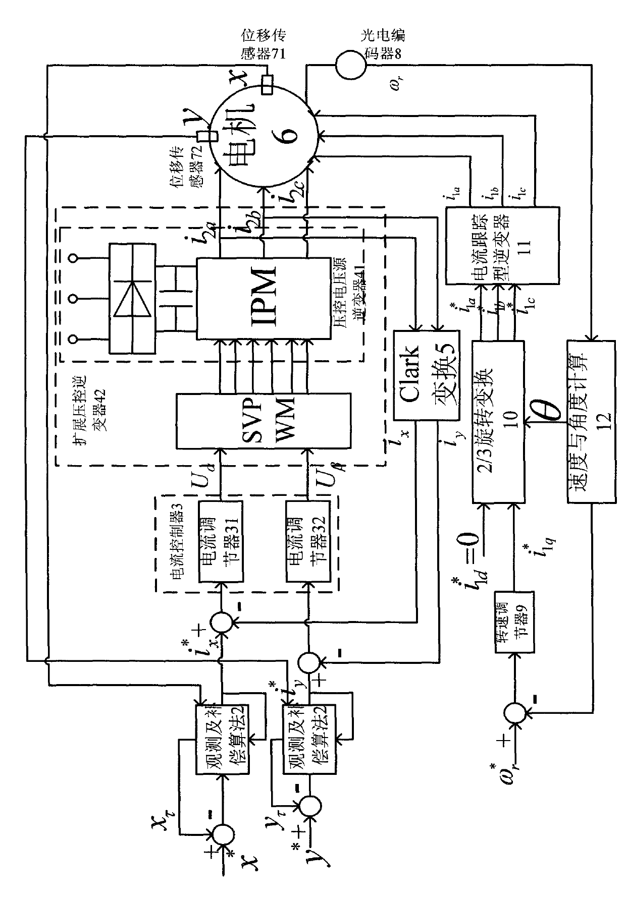
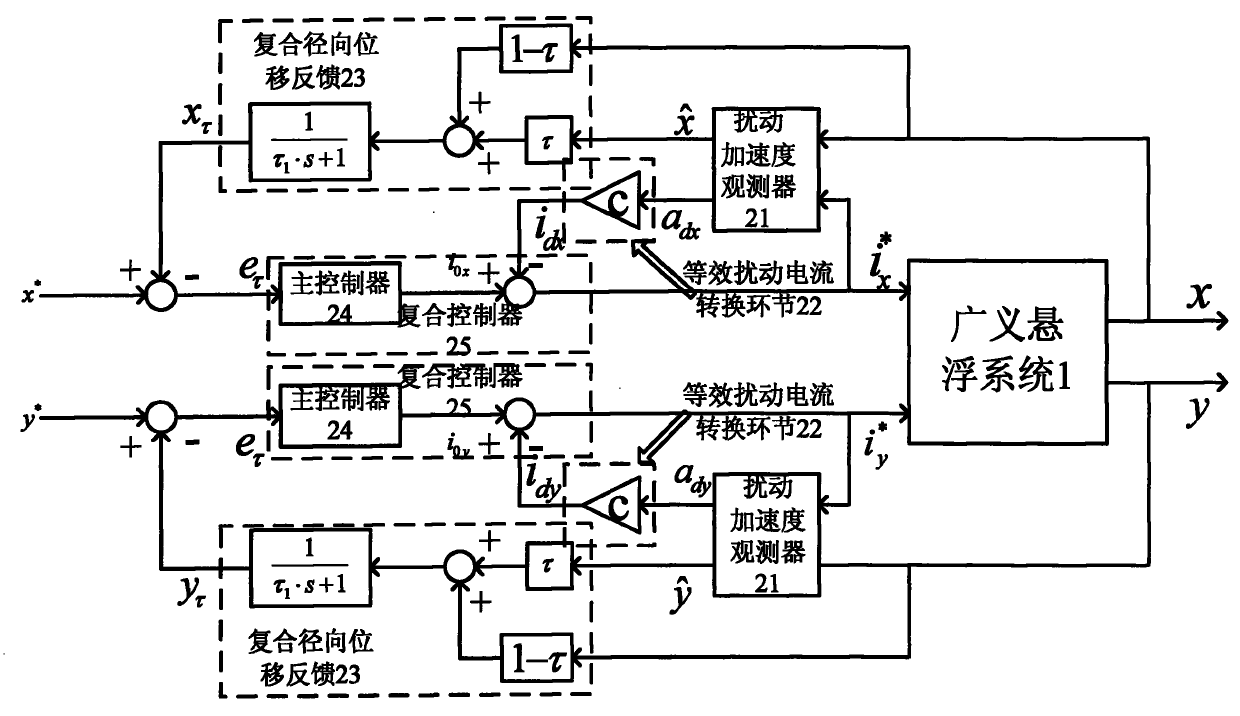
[0045] A bearingless permanent magnet synchronous motor suspension rotor equivalent disturbance current compensation control device, see figure 1 , figure 2 and Figure 3. figure 2 Among them, photoelectric encoder 8, speed regulator 9, 2 / 3 rotation coordinate transformation 10, current tracking inverter 11, speed and angle calculation 12 and motor 6 form an alternating pole bearingless permanent magnet synchronous motor torque control system. The control device includes a generalized levitation system 1 and a disturbance observation and compensation algorithm 2. The two observation and compensation algorithms 2 are connected in series before the generalized levitation system 1 and form a closed-loop structure; it is used for motor suspension in the displacement ring of a bearingless permanent magnet synchronous motor. The system takes control.

[0046] In this embodiment: the extended voltage-controlled inverter 42 is formed by the voltage-controlled voltage source inverte...


PUM


Abstract

The invention discloses a suspension rotor equivalent disturbance current compensation control device for a bearing-free permanent magnet synchronous motor. The control device is characterized in that: a generalized suspension system consists of an expended voltage controlled inverter, a current controller, a Clark transformer, a motor and a displacement sensor; observation and compensation algorithms are formed by connecting disturbance acceleration observers, equivalent disturbance current transforming links, composite radial displacement feedback, main controllers and composite controllers in sequence; two paths of observation and compensation algorithms are connected in series in front of the generalized suspension system and form a close-loop structure; and the control device is used for controlling a motor suspension system in a displacement ring of a bearing-free permanent magnet synchronous motor. The control device carries out the close-loop control on the displacement ring of the bearing-free permanent magnet motor suspension system of the consequent pole, and suppresses disturbance acting on the suspension system in a control mode of feedforward compensation. The control device observes disturbance acceleration generated by the suspension rotor of the motor because of disturbance effect through the disturbance observation algorithm in real time, and the algorithm does not dependent on a mathematical model of the suspension system and does not need to acquire specific forms of the disturbance in advance, so that the control device has wider adaptive range.

Description

technical field [0001] The invention relates to a control technology of a bearingless motor suspension system, in particular to an equivalent disturbance current compensation control device for a suspension rotor of an alternating pole bearingless permanent magnet synchronous motor. technical background [0002] The key difference between the alternating pole bearingless permanent magnet synchronous motor and the traditional bearingless permanent magnet synchronous motor lies in its special rotor structure, which enables the motor suspension system and torque system to be independent when the torque system adopts the rotor field oriented control strategy. control, which simplifies the control system design and improves system reliability. [0003] According to the existing literature, the research on ACPMSM mainly focuses on the following three aspects: [0004] 1. Research on the structural characteristics and working principle of the motor. Such as: analyze the suspensio...

Claims


Application Information

Patent Timeline
IPC IPC(8): H02P6/00H02P23/12H02P6/08
Inventor 丁强
Owner KUNSHAN PANGOLIN ROBOT
Learn More