
Method for starting three-phase modular multilevel inverter without auxiliary DC power supply

A multi-level converter and three-phase module technology, applied in the direction of output power conversion device, AC power input conversion to DC power output, electrical components, etc., can solve the problem of increasing equipment investment, restrictions, and inability to meet engineering needs, etc. problem, achieve the effect of reducing system complexity, shortening charging time, and increasing charging speed

Inactive Publication Date: 2010-08-04
ZHEJIANG UNIV
View PDF2 Cites 91 Cited by
  • Summary
  • Abstract
  • Description
  • Claims
  • Application Information

AI Technical Summary

Problems solved by technology

[0006] Obviously, this method not only requires a separate design of a suitable auxiliary DC charging power supply, increasing equipment investment; but also because the output voltage of the DC voltage source needs to be approximately equal to the voltage of the sub-module capacitor, so in high-voltage and large-capacity applications, this separate manufacturing The corresponding high-voltage auxiliary DC power supply is not easy to obtain, so it cannot meet the actual engineering needs
In addition, although the above-mentioned charging method using the auxiliary DC power supply can realize simultaneous charging between the three-phase bridge arms, it cannot realize simultaneous charging between the upper and lower two bridge arms of the same phase, and if the three-phase bridge arms are charged at the same time, the DC that needs to be provided The capacity of the power supply should also increase accordingly, thus further increasing the difficulty of manufacturing the auxiliary DC power supply
The existence of these problems greatly limits the application of other excitation starting methods that use auxiliary DC power supply to precharge the capacitors of each sub-module

Method used


Image

  • Method for starting three-phase modular multilevel inverter without auxiliary DC power supply
  • Method for starting three-phase modular multilevel inverter without auxiliary DC power supply
  • Method for starting three-phase modular multilevel inverter without auxiliary DC power supply

Examples


Embodiment Construction

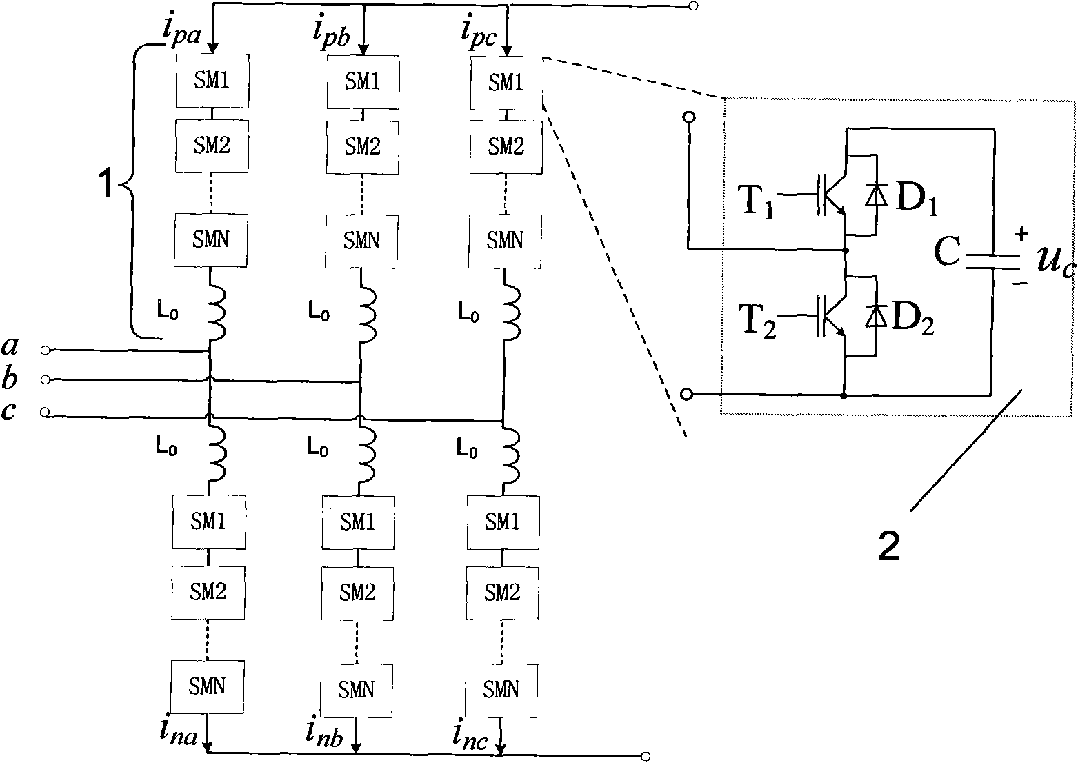
[0023] Such as figure 1 As shown, the three-phase modular multilevel converter is composed of six bridge arms in three phases a, b, and c, and each phase has two upper and lower bridge arms. Each bridge arm 1 consists of a reactor L 0 It is formed by cascading with N submodules 2. The sub-modules SM1~SMN have the same structure, and each sub-module is composed of the first power electronic switch T 1 , the second power electronic switch T 2 (T 1 , T 2 Select a power electronic switch with self-shutoff capability, usually IGBT, IGCT, GTO, etc., the present invention uses IGBT), a diode D connected in antiparallel with the first power electronic switch 1 , a diode D connected in antiparallel with the second power electronic switch 2 and DC capacitor C. Among them, the capacitor C and the first power electronic switch T 1 After being connected in series, it is connected with the second power electronic switch T 2 in parallel. The voltage across the capacitor C is u c ,...


PUM


Abstract

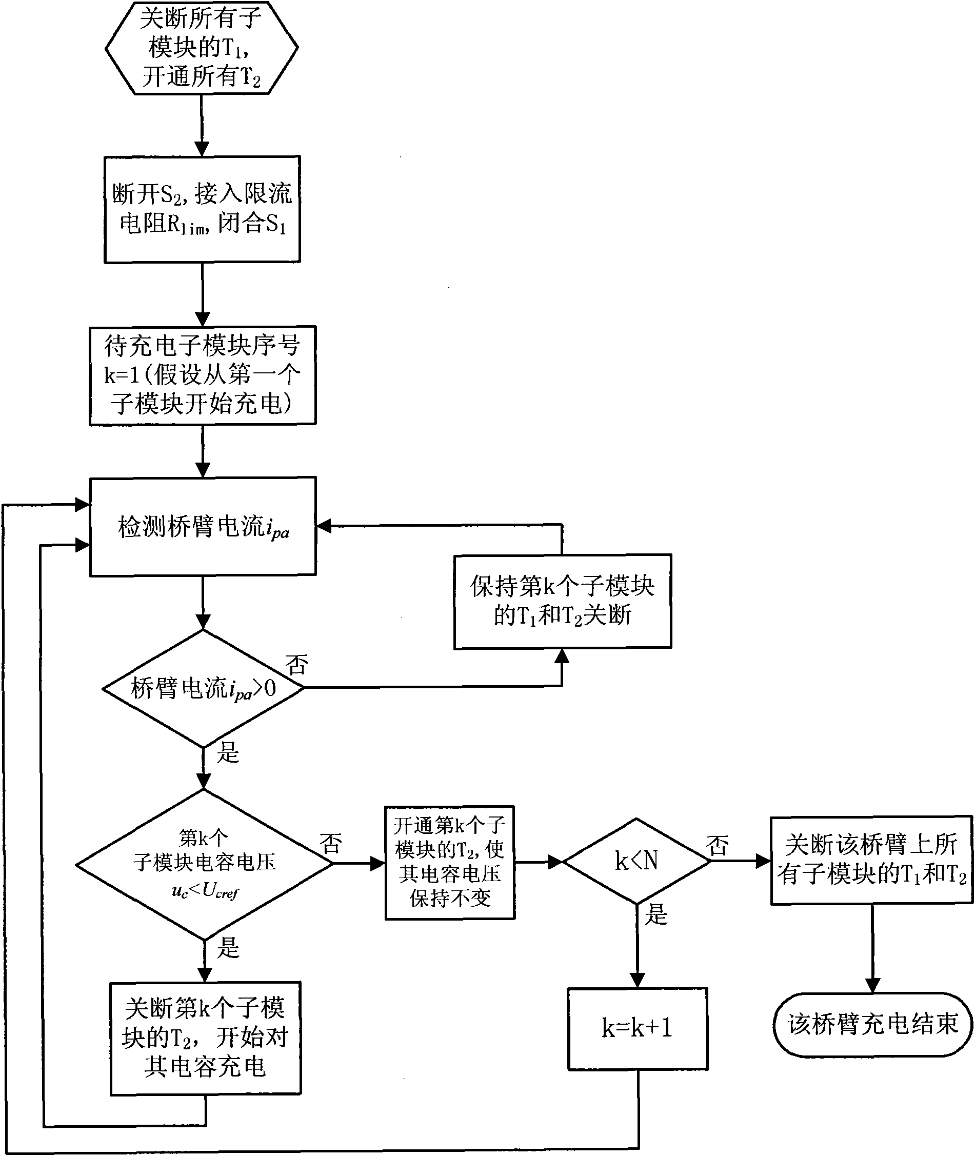
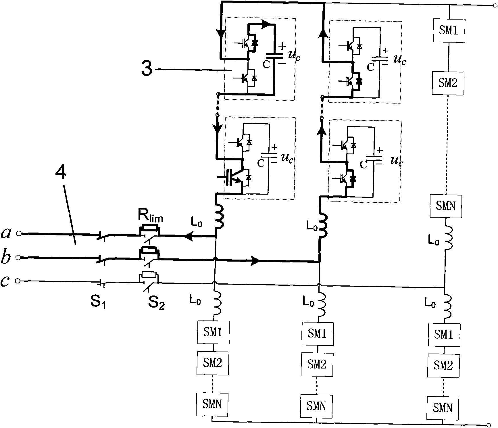
The invention discloses a method for charging and starting a three-phase modular multilevel inverter in a self-excitation way under the condition of no need of an auxiliary DC power supply. In the method, by adopting interphase currents generated by line voltages of an AC system among converter bridge arms, the process of charging capacitors of all the submodules on the bridge arms is completed by controlling switching on and switching off an upper electronic power switch and a lower electronic power switch in the submodules of all the bridge arms when current directions of the bridge arms and capacitor voltages of all the submodules are detected; and all the bridge arms can be simultaneously charged, so that the three-phase modular multilevel inverter can be quickly and normally started in the self-excitation way.

Description

technical field [0001] The invention relates to the technical fields of flexible power transmission and distribution of power systems, power electronics and user power, and in particular to a starting method for a three-phase modular multilevel converter. Background technique [0002] Modular multilevel converter (MMC) is a multilevel converter topology that has attracted much attention in recent years. It uses multiple submodules (submodules, SM) cascaded, and by controlling the input and disconnection states of each submodule separately, it can make the AC voltage waveform output by the converter contain many voltage steps to approach the sine wave to the maximum extent. Thereby reducing the harmonic content in the output voltage and reducing the waveform distortion to meet the harmonic requirements of the power grid. [0003] The basic structure of a three-phase modular multilevel converter (such as figure 1 Shown) is composed of three-phase six bridge arms, each phase ...

Claims


Application Information

Patent Timeline
IPC IPC(8): H02M1/36
CPCH02M2007/4835H02M7/4835
Inventor 徐政屠卿瑞翁华黄弘扬薛英林
Owner ZHEJIANG UNIV
Learn More