Energy-saving stove with ignition needle arranged at flame critical point
An ignition needle and critical technology, which is applied to household appliances, household stoves/stoves, lighting and heating equipment, etc., can solve the problems of short service life, melting of ignition needles, inconvenient installation of ignition needles, etc., to improve the utilization rate of heat energy, The effect of prolonging the service life and avoiding burning
- Summary
- Abstract
- Description
- Claims
- Application Information
AI Technical Summary
Problems solved by technology
Method used
Image

Examples
Embodiment 1
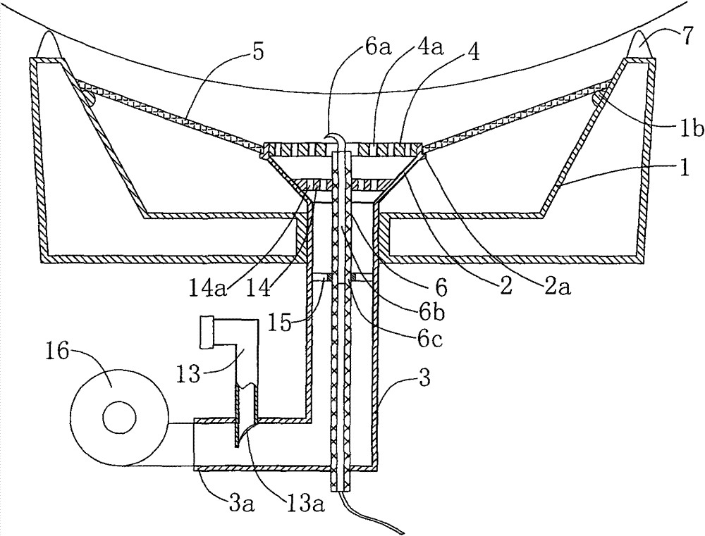
[0023] An energy-saving stove provided with an ignition needle at the critical point of the flame in this embodiment includes a furnace body 1 , a burner head 2 located in the center of the inner cavity of the furnace body 1 , a gas pipe 3 communicating with the burner head 2 and an ignition needle 6 .
[0024] Such as figure 1 As shown, a stove 4 is installed on the top of the burner 2, and the stove 4 is shaped on a gas hole 4a communicating up and down, and the gas in the gas pipe 3 is ignited after being ejected from the gas hole 4a. The gas holes 4a are evenly distributed on the stove plate 4, preferably four to twelve, and the appropriate aperture size of the gas holes 4a can play the role of combing the gas and preventing tempering.
[0025] The lower part of the burner 2 is connected with a gas pipe 3, and the lower end of the gas pipe 3 is formed with an air inlet 3a for connecting with a blower fan 16. The gas pipe 3 at the air inlet 3a place is connected with a gas...
Embodiment 2
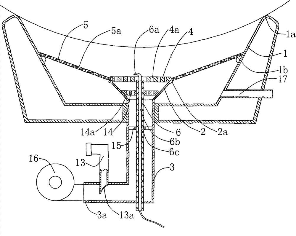
[0032] Such as figure 2 As shown, an energy-saving stove provided with an ignition needle at the critical point of the flame in this embodiment includes a furnace body 1, a burner head 2 located in the center of the inner cavity of the furnace body 1, a gas pipe 3 communicated with the burner head 2 and an ignition pin 6.
[0033] In the present embodiment, the structure of the burner 2, the gas pipe 3 and the ignition needle 6 is the same as that of the embodiment 1, except that the upper end of the furnace body 1 of the present embodiment forms a sealing support portion 1a which is sealed and connected with the bottom of the pot body, The pot body is installed on the sealing support part 1a, and a closed heating space is formed in the furnace body 1 .
[0034] Between the outer wall of the burner head 2 and the inner wall of the furnace body 1, a circular conical trapezoidal cover body 5 made of ceramic material is fixedly installed. The inner edge of the table-shaped cov...
Embodiment 3
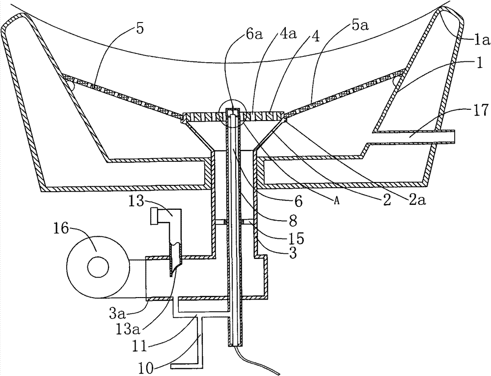
[0037] Such as image 3 As shown, an energy-saving stove provided with an ignition needle at the critical point of the flame in this embodiment includes a furnace body 1, a burner head 2 located in the center of the inner cavity of the furnace body 1, a gas pipe 3, an ignition needle 6 and an eternal flame mixed gas Tube 8.
[0038]A stove 4 is installed on the top of the burner 2, and the stove 4 is shaped on a gas hole 4a communicating up and down, and the gas in the gas pipe 3 is ignited after being ejected from the gas hole 4a. The gas holes 4a are evenly distributed on the stove plate 4, preferably four to twelve, and the appropriate aperture size of the gas holes 4a can play the role of combing the gas and preventing tempering.
[0039] The lower part of the burner 2 is connected with a gas pipe 3, and the lower end of the gas pipe 3 is formed with an air inlet 3a for connecting with a blower fan 16. The gas pipe 3 at the air inlet 3a place is connected with a gas inle...
PUM
 Abstract
Description
Claims
Application Information
 - R&D
- Intellectual Property
- Life Sciences
- Materials
- Tech Scout
- Unparalleled Data Quality
- Higher Quality Content
- 60% Fewer Hallucinations
Browse by: Latest US Patents, China's latest patents, Technical Efficacy Thesaurus, Application Domain, Technology Topic, Popular Technical Reports.
© 2025 PatSnap. All rights reserved.Legal|Privacy policy|Modern Slavery Act Transparency Statement|Sitemap|About US| Contact US: help@patsnap.com