
Boosting method for synchronization without insulating photovoltaic grid-connected inverters

A technology of inverters and photovoltaics, applied in photovoltaic power generation, light radiation generators, generators/motors, etc., can solve the problems of output filter capacitor C and frequent impacts of inverter bridges, etc., to reduce the impact current and volume , space-saving effect

Active Publication Date: 2010-07-28
SUNGROW POWER SUPPLY CO LTD
View PDF4 Cites 32 Cited by
  • Summary
  • Abstract
  • Description
  • Claims
  • Application Information

AI Technical Summary

Problems solved by technology

[0005] Aiming at the deficiencies of the prior art, the present invention designs and develops a non-isolated photovoltaic grid-connected inverter grid-connected start-up method that saves the AC buffer circuit and improves system reliability. In the case where the output filter circuit of the inverter remains unchanged Under this condition, without adding any buffer device, it can solve the problem of the impact current on the capacitor C generated at the moment of the AC switch pull-in, and at the same time solve the problem of frequent switching on and off of the system and the repeated turning on and off of the AC switch when the sunlight intensity is insufficient The problem of frequent impact of the variable bridge greatly improves the reliability of the system

Method used


Image

  • Boosting method for synchronization without insulating photovoltaic grid-connected inverters
  • Boosting method for synchronization without insulating photovoltaic grid-connected inverters
  • Boosting method for synchronization without insulating photovoltaic grid-connected inverters

Examples


Embodiment 1

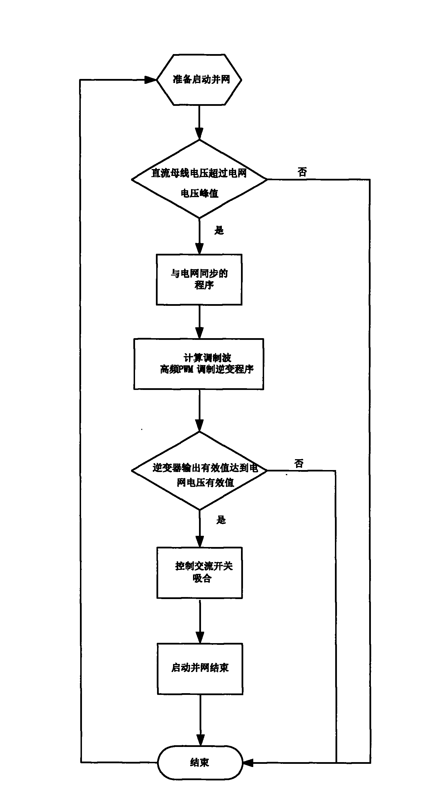
[0023] In the present invention, a DC voltage sensor is installed on the DC input side, an AC switch is installed on the AC output side, and an AC voltage sensor is installed on the side of the AC switch close to the power grid. On, the DC voltage sensor detects the inverter input DC bus voltage amplitude, and the AC voltage sensor detects the grid voltage amplitude, frequency and phase. When the voltage amplitude of the DC bus voltage input by the inverter exceeds the peak value of the grid voltage, the inverter control circuit calculates the grid voltage phase and frequency according to the DC bus voltage amplitude, grid voltage amplitude, phase, and frequency by the following formula To keep the synchronous inverter modulating wave, V inv =M sin(wt+θ); w=2πfV inv is the modulation wave; M is the amplitude of the modulation wave; f is the frequency of the grid voltage; θ is the angle consistent with the phase of the grid voltage;

[0024] According to the above formula, wh...

Embodiment 2

[0027] In the present invention, a DC voltage sensor is installed on the DC input side, an AC switch is installed on the AC output side, and an AC voltage sensor is installed on the side of the AC switch close to the power grid. On, the DC voltage sensor detects the inverter input DC bus voltage amplitude, and the AC voltage sensor detects the grid voltage amplitude, frequency and phase, and transmits the collected data to the inverter control circuit for processing. When the voltage amplitude of the DC bus voltage input by the inverter exceeds the peak value of the grid voltage, the inverter control circuit calculates the grid voltage phase and frequency according to the DC bus voltage amplitude, grid voltage amplitude, phase, and frequency through the following formula Synchronous inverter modulation wave, V inv =M sin(wt+θ); w=2πf

[0028] V inv is the modulation wave; M is the amplitude of the modulation wave; f is the frequency of the grid voltage; θ is the angle consis...


PUM


Abstract

The invention relates to a boosting method for synchronization without insulating photovoltaic grid-connected inverters. The inverter operates independently before the integration into the grid. The AC switch is kept disconnected while the DC voltage sensor detects the value of voltage amplitude of the DC bus input by the inverter. The AC voltage sensor detects the amplitude, frequency and phase of the grid voltage. When the voltage amplitude input into the DC bus by the inverter exceeds the peak voltage of the grid, the inverter manages the circuit to calculate, according to the voltage amplitude of the DC bus and the amplitude, frequency and phase of the grid voltage, and get the inverted modulating wave that is synchronized with the phase and frequency of the grid voltage. When the DC inverter voltage and the grid voltage become identical in frequency, phase and amplitude, and the voltage amplitude of the bus is permissible for the synchronization, the inverter controls the circuit and the actuation of the AC switch and starts the operation of the synchronization. The invention is simple in structure and can save power as well as enhance the system stability.

Description

technical field [0001] The invention relates to a grid-connecting method of a photovoltaic grid-connected inverter, in particular to a grid-connected starting method without isolating a photovoltaic grid-connected inverter. Background technique [0002] At present, the grid-connected start-up conditions of non-isolated photovoltaic grid-connected inverters are: for a single-stage system, the open circuit voltage of the photovoltaic array is greater than the peak value of the grid voltage; for a multi-level system with a boost circuit, the input bus voltage after boosting is greater than the grid voltage voltage peak. Once the grid-connected start condition is reached, the AC switch (contactor or relay) is closed, so that the inverter is connected to the grid and starts grid-connected power generation. This direct grid-connected logic control method will make the output voltage of the solar cell array fluctuate up and down at the lowest point of the voltage that meets the gr...

Claims


Application Information

Patent Timeline
Patent Type & Authority Applications(China)
IPC IPC(8): H02J3/40H02J3/42H02N6/00
CPCY02E10/563Y02E10/56
Inventor 曹仁贤倪华梅晓东
Owner SUNGROW POWER SUPPLY CO LTD
Learn More