
Cooling system of automobile

A technology of automobile cooling and heat dissipation unit, which is applied in the direction of engine cooling, coolant flow control, cylinder, etc., which can solve the problems of large cooling capacity, low thermal efficiency, and large fuel consumption of the automobile cooling system, so as to improve the performance of the cooling system, Effects of improving fuel economy and improving inflation efficiency

Active Publication Date: 2010-07-28
CHERY AUTOMOBILE CO LTD
View PDF6 Cites 4 Cited by
  • Summary
  • Abstract
  • Description
  • Claims
  • Application Information

AI Technical Summary

Problems solved by technology

[0005] In order to solve the problem of overheating of the engine under extreme working conditions, the traditional automobile cooling system is designed to make the automobile cooling system circulate continuously with the operation of the engine, that is, to let the coolant reciprocate in the water channels of the engine block and cylinder head in sequence Circulating flow absorbs heat, which often causes the cooling capacity of the car cooling system to be too large, resulting in slow start and warm-up speed of the car. When the car is running at low speed or low load, the cooling capacity is excessive, the thermal efficiency is reduced, the fuel consumption is large, and the emission is poor.

Method used


Image

  • Cooling system of automobile
  • Cooling system of automobile
  • Cooling system of automobile

Examples


Embodiment Construction

[0021] The present invention will be further described below in conjunction with the accompanying drawings and specific embodiments, but not as a limitation of the present invention.

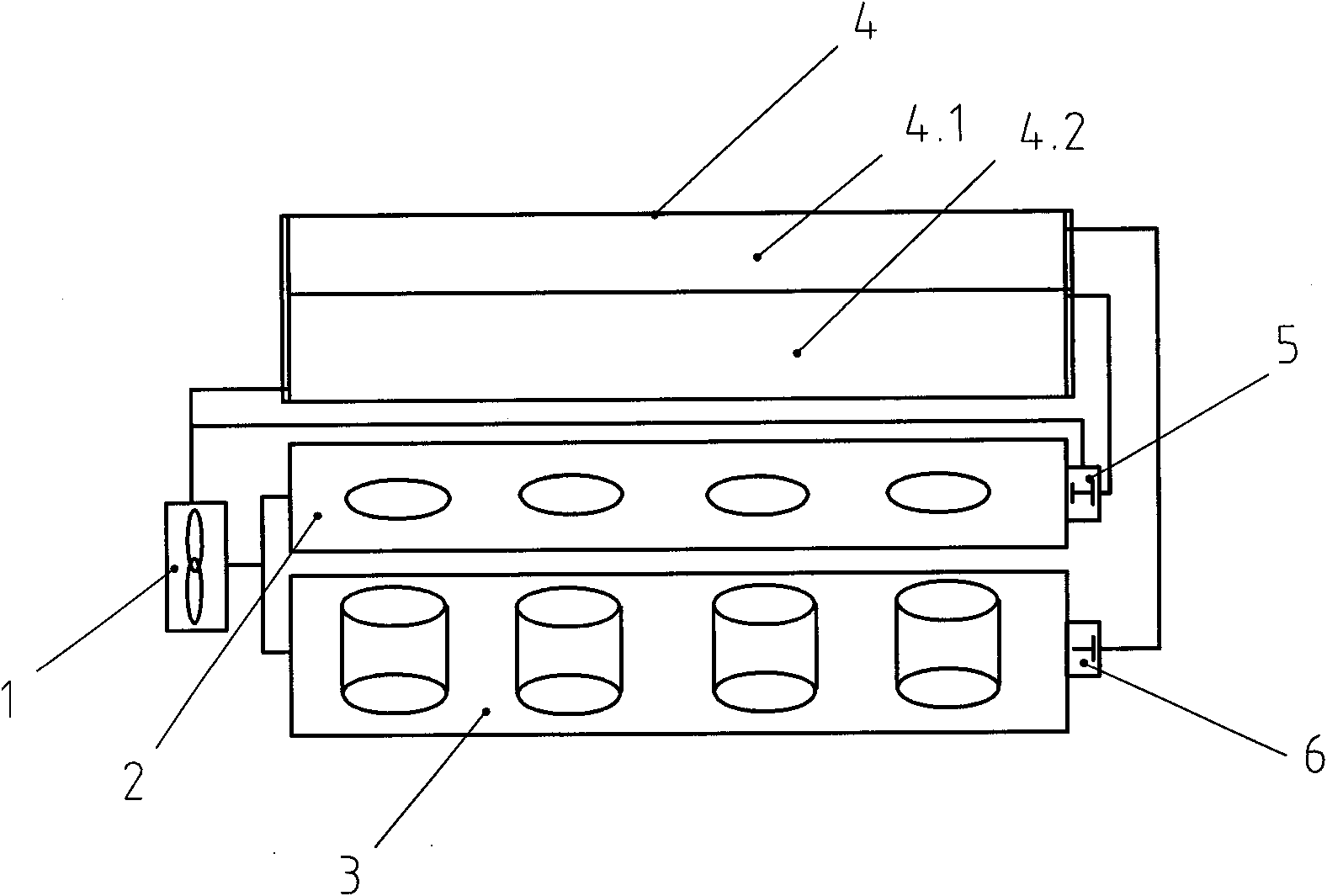
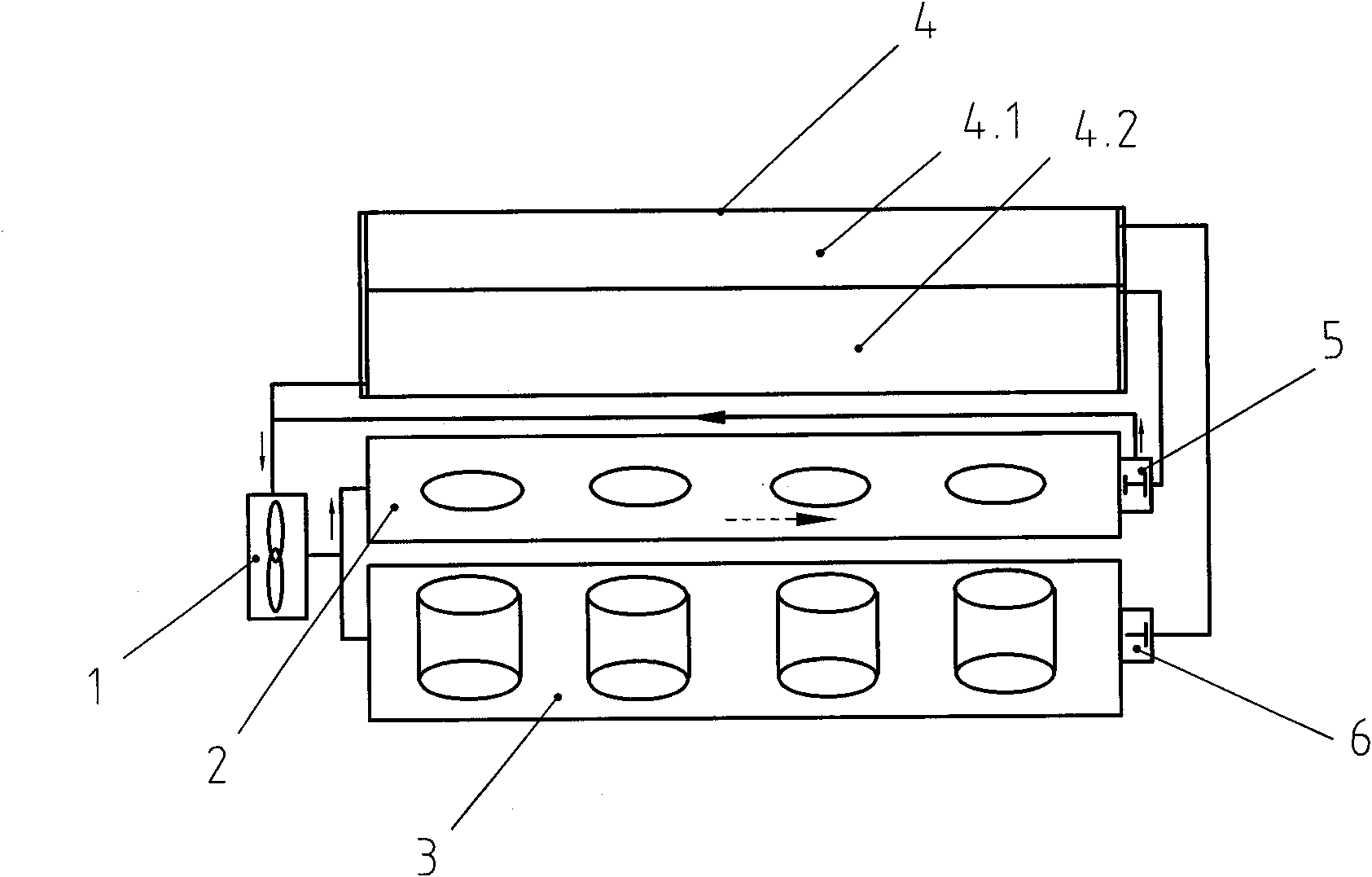
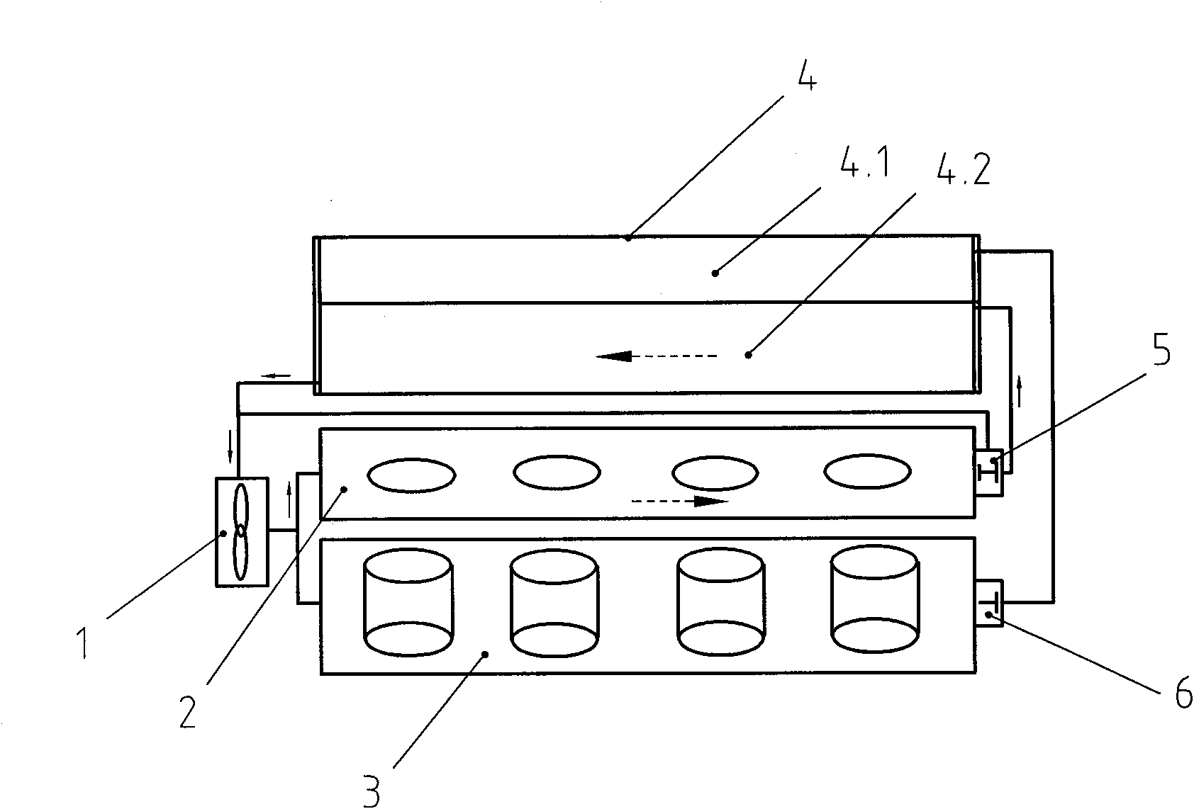
[0022] Such as figure 1 As shown, the automobile cooling system described in the embodiment of the present invention is connected with the internal circulation pipeline of the cylinder body 3 and the cylinder head 2, and it includes a water pump 1, a radiator 4, a thermostat and connecting pipelines. Wherein, the water outlet of the water pump 1 is respectively connected to the internal circulation pipeline of the cylinder body 3 and the cylinder head 2, and then connected to the water inlet of the radiator 4 through respective thermostats, and finally connected to the water outlet of the radiator 4 through the water outlet of the radiator 4. The water inlet of the water pump 1.

[0023] In this example, the cylinder head thermostat 5 and the cylinder block thermostat 6 are used. These two wax-...


PUM


Abstract

The invention discloses a cooling system of an automobile, which is connected with inner circulation pipelines of a cylinder body and a cylinder cover. The cooling system comprises a pump, a radiator, a thermolator and a connecting pipe, wherein the radiator comprises two independent radiating units which are respectively provided with a water inlet, and are commonly provided with a water outlet, the thermolator comprises a cylinder cover thermolator and a cylinder body thermolator, the water outlet of the pump is divided into two paths, wherein one path passes through the inner circulation pipeline of the cylinder body, then is connected with the water inlet of one independent radiating unit through the cylinder body thermolator, and the other path passes through the inner circulation pipeline of the cylinder cover, and is connected with the water inlet of the other independent radiating unit through the cylinder cover thermolator, and finally is connected with the water inlet of the pump through the water outlet of the radiator. The invention can ensure that an engine can work under rational temperature distribution, can improve the speed of a warming up, can ensure that the automobile can work at the high temperature under various working conditions, effectively cools the performance of the system, improves the fuel economy, and reduces the discharge.

Description

technical field [0001] The invention relates to a cooling system, in particular to an automobile cooling system. Background technique [0002] As a means of transportation, automobiles play a very important role in modern industrial society. How to keep the car running in a normal state is very important, and the car cooling system is one of the key elements to ensure the normal operation of the car. The function of the car cooling system is to ensure that the engine can quickly reach the ideal operating temperature and keep it in this temperature range regardless of changes in the environment and working conditions. In other words, the engine must be able to run at the same high speed whether in extremely cold or hot conditions, whether in a traffic-jammed urban environment or at full speed on the highway. [0003] The traditional car cooling system is connected to the cylinder block and cylinder head, which includes the water pump, radiator, thermostat and the pipes conn...

Claims


Application Information

Patent Timeline
Patent Type & Authority Applications(China)
IPC IPC(8): F01P5/10F01P7/14F02F1/14F02F1/40
Inventor 邹进解正斌江雪峰
Owner CHERY AUTOMOBILE CO LTD
Learn More