Tent house

A technology for tents and skeleton parts, applied in the field of tents, can solve problems such as inability to solve geometrical shape contradictions, unfavorable large venues, poor effects, etc., and achieve the effect of reducing the possibility of rainwater retention

Inactive Publication Date: 2010-07-28
劳斯伯格建筑科技(上海)有限公司
View PDF0 Cites 4 Cited by
  • Summary
  • Abstract
  • Description
  • Claims
  • Application Information

AI Technical Summary

Problems solved by technology

However, because the shape of the traditional tent structure is a straight material, after the large piece of flexible material and its skeleton are fixed, the surface tension is not enough, and it is easy to form a sag phenomenon, that is, the flexible material is sunken into the house, and at the same time, it is larger outdoors. Under the wind, it is easy to cause the concentration of force due to the large windward side of the straight roof, and the roof of flexible material is easy to deform and be blown as a whole to pull or squeeze the roof skeleton, which is easy to cause tent damage. to destroy
[0003] At the same time, the height and span of this type of room are also limited by straight materials, which cannot solve the geometric contradiction of having both a large span and a relatively high height, and the disadvantage of wind damage is that it has a large span or height. It is more obvious in the tent room, so it is not conducive to the needs of large venues
In this regard, people increase the use of building components such as fixings and internal pillars, but the use of these components not only increases the cost of construction and the effect is not good, but also causes the loss and limitation of the span, height and internal space of the house, and the utilization rate is reduced.
At the same time, this method of adding components cannot solve the contradiction that large-scale venues have both large spans and high heights and can resist relatively large winds.

Method used


Image

  • Tent house
  • Tent house
  • Tent house

Examples


Embodiment Construction

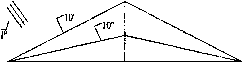
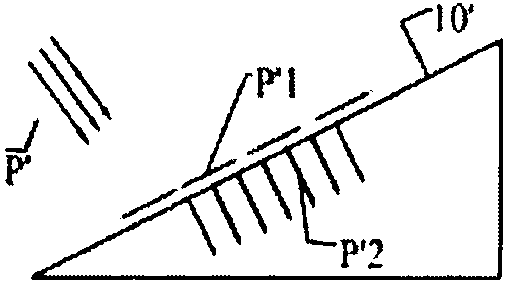
[0026] figure 1 The schematic diagram of the roof of the existing tent shown, as shown in the figure, the straight frame 10' in the roof is built into a triangle relative to the house, and the external wind force P' directly acts on the straight frame 10' of the roof. pass figure 2 The force analysis shown shows that the wind force P' can be decomposed into a component force P'1 upward along the straight frame 10' and a component force P'2 perpendicular to the direction of the straight frame 10'. From figure 2 It can be clearly understood that due to the use of the straight frame 10', all component forces will accumulate in one direction to form a larger resultant force. These larger resultant forces will inevitably require sufficient support from the tent, such as additional internal columns , support frame, etc. to resist the destructive force formed by the resultant force. These additional parts not only increase the cost and take up space, but also increase the weight...


PUM


Abstract

The invention discloses a tent house, which consists of a plurality of cross section parts consisting of upright post parts and roof framework parts, and a flexible roof material and wall part which covers and is fixed on a framework, wherein each roof framework part of each cross section part is in an arc shape on the cross section of the tent house, and two ends of the roof framework part are connected with upper ends of the upright post parts; the arc roof framework parts are symmetrical about the centers of the cross section parts; simultaneously, each arc roof framework part at least consists of two same arc frameworks through connection; the arc frameworks can be made of tubular sections and are connected and fixed in an insertion mode; and straight roof framework parts can also be connected between the arc roof framework parts and the upright post parts to serve as roof frameworks on the outer edges of the tent house. The tent house with the structure is easy to tension and arrange due to the flexible roof material, and simultaneously can be applied to larger span, height and space to resist larger external wind force.

Description

technical field [0001] The invention relates to a tent, in particular to a tent structure which is suitable for outdoor installation and adopts flexible materials as the roof and its component structure. Background technique [0002] As a practical architectural form, tents are usually composed of rigid straight materials such as beams, roof frames and columns of the house. These straight beams and roof frames are built into a triangle, that is, the straight rigid roof frame extends from the center of the house to The two sides extend and connect the beams and related columns, and then use a large piece of flexible material as the roof and fix it on the roof skeleton connecting the beams, while the enclosure walls of the house can be closed or semi-closed according to needs. Since the tent is composed of straight materials, the processing and transportation costs of each material are low. At the same time, it is relatively easy to build and disassemble, and has the character...

Claims


Application Information

Patent Timeline
Patent Type & Authority Applications(China)
IPC IPC(8): E04H15/18E04H15/36
Inventor 弗理德理希·劳斯伯格
Owner 劳斯伯格建筑科技(上海)有限公司
Why Eureka
Try Eureka