Clamping device of injection head of continuous string coiled tubing

A technology of oil pipe and oil cylinder, which is applied in the field of coiled tubing clamping device of injection head, which can solve problems such as clamping deflection, uneven force on clamping block, weakening force on saddle-shaped clamping block, etc., and achieve strong clamping force , improve the effect, easy to align the effect of the wellhead

Active Publication Date: 2012-07-04
中石化四机石油机械有限公司 +1
View PDF0 Cites 0 Cited by
  • Summary
  • Abstract
  • Description
  • Claims
  • Application Information

AI Technical Summary

Problems solved by technology

These two coiled tubing clamping devices for the injection head have a common disadvantage: the pressure area of ​​the saddle-shaped clamping block is too large, and it cannot ensure that each clamping block is fully in contact with the integral pressure block to obtain the balance from the oil cylinder. The clamping force, and the uneven force on each clamping block causes the coiled tubing to fail to align with the wellhead directly below the center hole of the blowout preventer during the process of being clamped and lowered into the wellhead; especially when a certain clamping block is severely worn Or inclusion of hard foreign matter, wear and deformation of the integral pressure block, or failure of a certain clamping cylinder associated with each other, the force on the saddle-type clamping block of the injection head will be significantly weakened, and it will be very uneven, causing the coiled tubing to be clamped and deflected , cannot accurately align the wellhead directly below the center hole of the blowout preventer, resulting in abnormal operation of coiled tubing equipment

Method used


Image

  • Clamping device of injection head of continuous string coiled tubing
  • Clamping device of injection head of continuous string coiled tubing
  • Clamping device of injection head of continuous string coiled tubing

Examples


Embodiment Construction

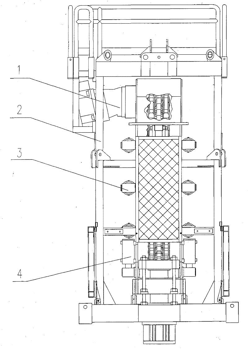
[0017] Attached below Figure 1-5 The specific embodiment of the present invention will be further described.

[0018] see figure 1 , figure 2 and image 3 The coiled tubing clamping device of the injection head is supported by the frame 2 and the frame side plate 19. When the coiled tubing 5 is lowered into the oil well, the hydraulic motor works under the control of the hydraulic system of the equipment. Transmission to the drive shaft 6 in the drive box 1, so as to drive the two drive sprockets 7 mounted on the drive shaft 6 to rotate in opposite directions, and then drive the two pairs of chains 9 to move downward, and the four sets of tension cylinders 4 push the shaft 16 The tensioning sprocket 15 on the top makes the chain 9 tense. At the same time, under the control of the hydraulic system, the three pairs of clamping cylinders 3 are pressurized sequentially from top to bottom, driving the clamping cylinders 3 to shrink, and the clamping cylinders 3 and the shaft 1...


PUM


Abstract

The invention relates to an injection head device of a continuous string coiled tubing, which comprises clamping cylinders, tensioning cylinders, drive sprocket wheels, saddle shaped clamping blocks and chains. A cylinder head and a piston rod head of three pairs of clamping cylinders of the device are respectively connected through a shaft, a bearing bracket which can rotate on the shaft is arranged on each shaft, a sliding block is respectively arranged on both ends of the shaft, a bearing frame body which can rotate on a pin roll is respectively arranged on two end of each bearing bracket through the pin roll, and a clamping bearing which can rotate on the pin roll is respectively arranged on each bearing frame body through the pin roll. A plurality of clamping bearings are separated into three parts relatively independent, a clamping mechanism is separately controlled by three sets of clamping cylinders respectively, so that when the injection head goes up and down the continuous string coiled tubing, the upper clamping cylinder, the middle clamping cylinder and the lower clamping cylinder can sequentially load pressure or unload pressure. As a result, the clamping force can concentrate on the three parts so as to ensure that when the continuous string coiled tubing is clamped, strong clamping force can be generated, and the loading force is balanced without deflection and can be easily aligned with the well head. Therefore, the invention solves the technical problem of difficult alignment with the well head during operation of the continuous string coiled tubing operation device for quite a long time.

Description

technical field [0001] The invention relates to the field of oil drilling equipment, in particular to a clamping device for a coiled tubing of an injection head. Background technique [0002] Coiled tubing equipment is widely used in oil and gas field workover, drilling, well completion, well logging and other operations, and plays an increasingly important role in oil and gas field exploration and development. Coiled tubing equipment is known as "universal operation" equipment. The coiled tubing clamping device of the injection head is a key part of the coiled tubing operation equipment. The hydraulic motor rotating in the forward and reverse directions drives the sprocket to work, and the coiled tubing is clamped by the saddle-shaped clamping block between the chain links, so that it is connected with the chain Movement to realize coiled tubing running into the well or lifting out of the wellhead. At present, the basic structure of the injection head clamping device is to...

Claims


Application Information

Patent Timeline
Patent Type & Authority Patents(China)
IPC IPC(8): E21B19/00
Inventor 王峻乔张保弟池胜高孙晓明李德清李红罗东
Owner 中石化四机石油机械有限公司
Why Eureka
Try Eureka