
Reserved chamber simulating test piece manufacturing die assembly and method used for manufacturing test piece

A technology of mold assembly and test piece, which is applied in the field of simulated test piece mold assembly and its use in the preparation of simulated test pieces, can solve the problems of sample quality deterioration, sample damage, and difficulty in grasping the percussion force, etc. Achieve the effects of reducing impact and damage, easy demoulding process, and easy demoulding operation

Inactive Publication Date: 2013-09-04
SHANDONG UNIV OF SCI & TECH
View PDF6 Cites 9 Cited by
  • Summary
  • Abstract
  • Description
  • Claims
  • Application Information

AI Technical Summary

Problems solved by technology

Since the main cementitious material in the experimental sample is cement, its coagulation and solidification is an exothermic reaction process. If the demoulding time of the sample is too late, it is likely to miss the best curing time for the demoulded sample, which will cause the quality of the sample to deteriorate. become worse
However, the demoulding time is too early. At this time, the solidification and solidification of the sample is in the initial stage, and the sample has not yet fully hardened. In addition, the solidification and solidification process of cement is a change process of volume shrinkage. At this time, the volume of the sample is relatively large. The adhesion between the inner walls is also relatively large. Using a wooden stick to knock down the edge of the mold is difficult to grasp, and it is easy to cause damage to the sample.
In a word, it is very inconvenient to demould the sample made of the reserved chamber simulation test piece mold used in the prior art.

Method used


Image

  • Reserved chamber simulating test piece manufacturing die assembly and method used for manufacturing test piece
  • Reserved chamber simulating test piece manufacturing die assembly and method used for manufacturing test piece
  • Reserved chamber simulating test piece manufacturing die assembly and method used for manufacturing test piece

Examples


Embodiment Construction

[0040] In conjunction with the accompanying drawings, the embodiment of the prepared mold assembly of the reserved chamber simulation test piece of the present invention is described in detail as follows:

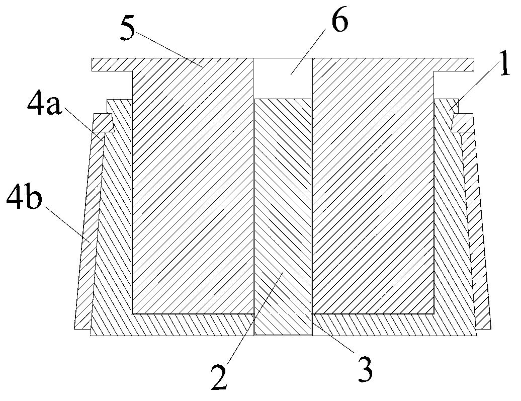
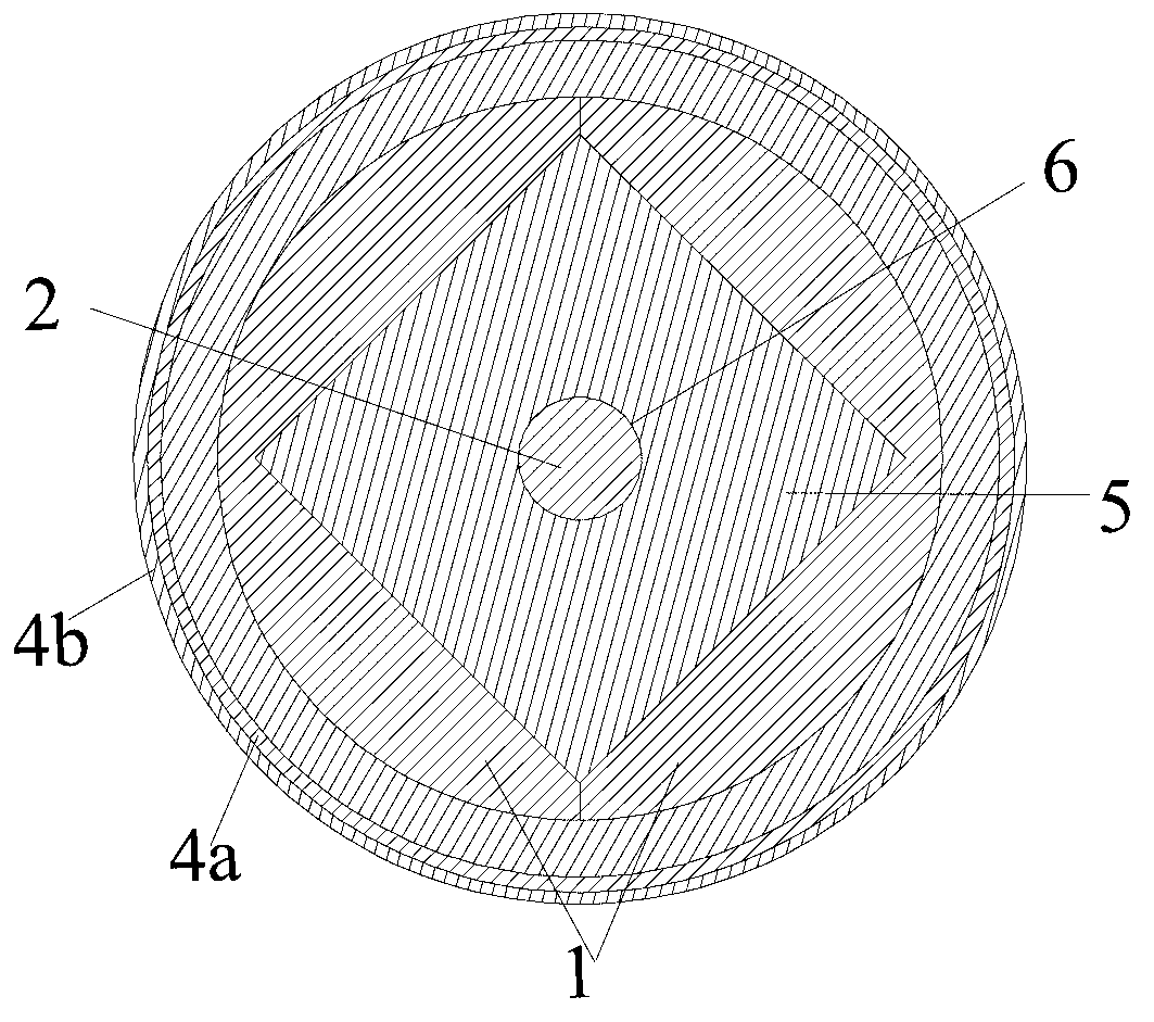
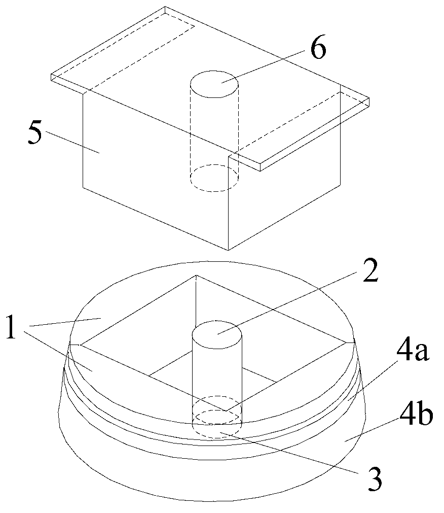
[0041] Such as figure 1 As shown, the preparation mold assembly of the reserved chamber simulation test piece of the present invention includes a model shell 1 of a split structure composed of two symmetrical parts, a solid cylinder 2, a circular through hole 3, and a first clamp 4a , the second clamp 4b, the pressure bearing plate 5, and the cylindrical housing chamber 6. An annular groove is arranged on the outer peripheral surface of the upper part of the above-mentioned model shell 1, and the above-mentioned annular groove is in the shape of a rounded truncated cone as a whole, and the diameter of its cross section is from thick to thin from top to bottom; the above-mentioned clamp includes a first clamp 4a and The second clamp 4b, wherein the first clamp 4a is an open...


PUM


Abstract

The invention discloses a reserved chamber simulating test piece manufacturing die assembly and a method used for manufacturing a test piece. The die assembly comprises a model shell, a solid cylinder, a round through hole, clamps, a bearing plate and a cylinder containing cavity, wherein the model shell has a splitting structure and is formed by two symmetrical parts; a hexahedral sample adding cavity is arranged at the upper part of the model shell, and a press is used for compacting and shaping a sample in the cavity by the bearing plate. The die assembly has a simple structure, and is convenient to disassemble, and the sample can be subjected to mold release conveniently. The invention also discloses the method for manufacturing the test piece by adopting the reserved chamber simulating test piece manufacturing die assembly. The method comprises the steps of assembling a mold, adding the sample, pressurizing the sample, separating the mold, and disassembling the mold. According to the test piece manufactured by adopting the method for manufacturing the test piece by the die assembly, the test piece can be subjected to mold release conveniently, and the pressurized shaping effect of the test piece is good.

Description

technical field [0001] The invention relates to a mold assembly for a simulated test piece and a method for preparing the simulated test piece, in particular to a mold assembly for preparing a simulated test piece with a reserved chamber and a method for preparing the test piece. Background technique [0002] In engineering construction, it is often necessary to study the deformation and evolution of the surrounding rock after chamber excavation. Therefore, it is necessary to carry out relevant research on reserved chambers in advance to conduct simulation tests on discontinuous rupture areas, cracks, and support conditions. In the laboratory, iron powder, barite powder, gypsum powder, lime powder, quartz sand, river sand, clay, wood chips, etc. are generally used with cement, zinc oxide, paraffin, rosin, alcohol, white latex, resin, etc., according to A certain ratio is mixed into a slurry material, and then made into a test piece, and then the next step of the experimental...

Claims


Application Information

Patent Timeline
IPC IPC(8): G01N1/28
Inventor 魏平赵同彬谭云亮尹延春于凤海盛园园
Owner SHANDONG UNIV OF SCI & TECH
Learn More