
Unpowered biological filtration tower

A biological filter tower and power technology, applied in sustainable biological treatment, biological water/sewage treatment, water/sludge/sewage treatment, etc., can solve the problems of high operation and maintenance costs, affecting the surrounding environment, and high operating costs, achieving Improve the hydraulic retention time, increase the specific surface area, and increase the effect of increasing the film hanging time

Inactive Publication Date: 2010-07-21
PLA UNIV OF SCI & TECH
View PDF0 Cites 8 Cited by
  • Summary
  • Abstract
  • Description
  • Claims
  • Application Information

AI Technical Summary

Problems solved by technology

The defects of the existing biological aerated filter are as follows: 1) due to the open structure, it is easy to generate odor and mosquitoes, which affects the surrounding environment; 2) the filter material is usually densely arranged and easy to block, so it is necessary to add backwashing facilities, Resulting in high operating costs and complicated maintenance and management
The existing tower-type biological filter and biological aerated filter still have a common defect: fan power facilities need to be configured, so energy consumption is large, and operation and maintenance costs are high

Method used


Image

  • Unpowered biological filtration tower
  • Unpowered biological filtration tower
  • Unpowered biological filtration tower

Examples


Embodiment 1

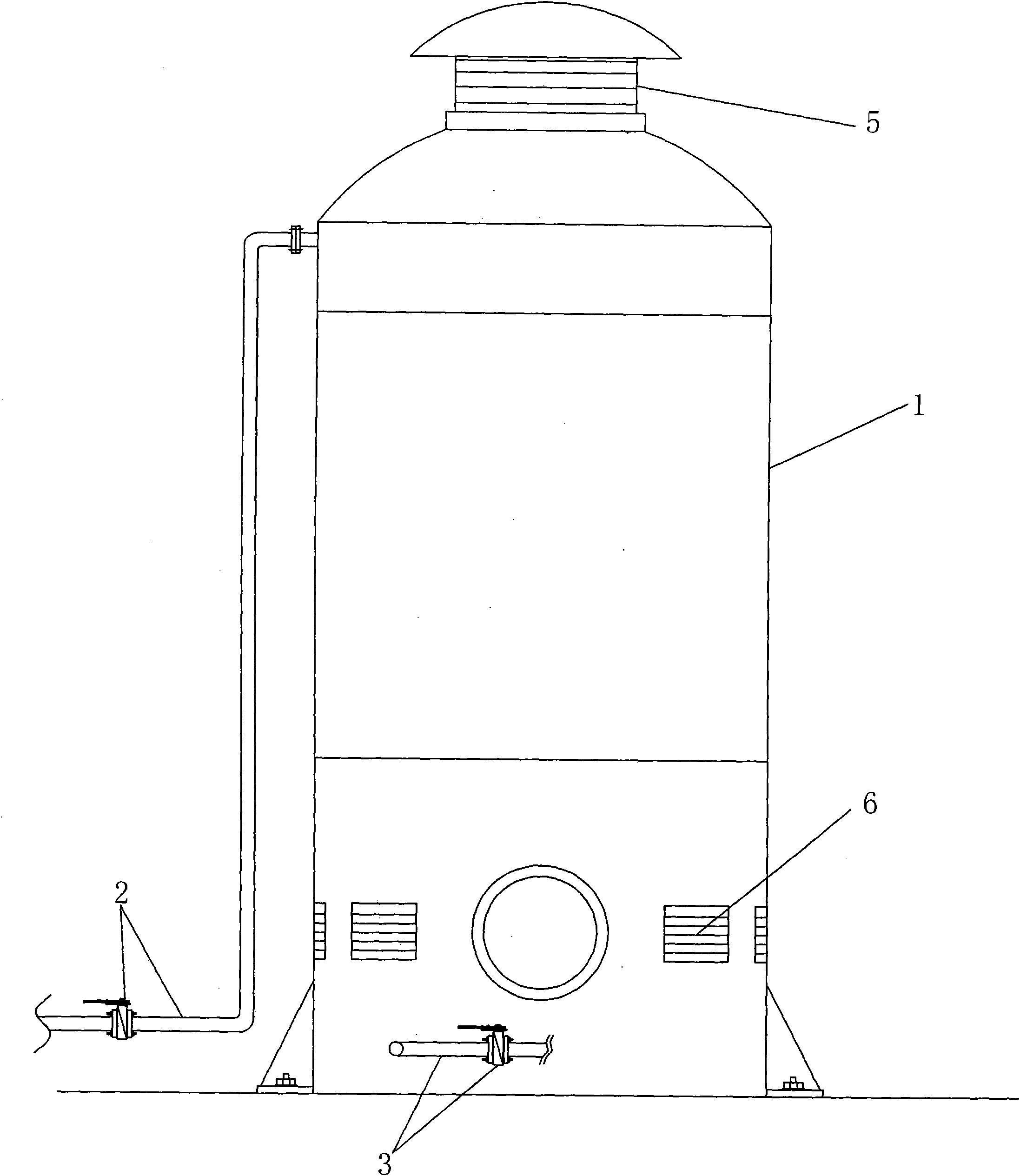
[0021] The non-powered biological filter tower of the present embodiment, as image 3 and Figure 4 As shown, it includes a tower body 1, a water inlet pipe 2 and an outlet pipe 3 respectively arranged on the upper and lower parts of the tower body 1, a water distributor 4 arranged on the upper part of the tower body 1 and connected to the water inlet pipe 2, and filled in the tower body 1. Inside and located at the filter material layer below the water distributor 4. A wind cap 5 is arranged on the top of the tower body 1, and an air inlet 6 is opened on the side wall of the lower part of the tower body. The air inlet 6 adopts shutters. The water distributor 4 has a built-in spin nozzle. The tower body 1 is processed into three sections by steel plates and connected by flanges; the inner wall of the tower body 1 is lined with glass fiber; the outer wall of the tower body 1 is painted with two coats of anti-corrosion paint and sprayed with metal topcoat.

[0022] like Fi...

Embodiment 2

[0025] The unpowered biological filter tower structure of the present embodiment is basically the same as the unpowered biological filter tower in Embodiment 1, the difference is: as Figure 7 As shown, the inclined tube 8 of the elastic filter material layer is replaced by an inclined plate 14.


PUM


Abstract

The invention relates to an unpowered biological filtration tower, which belongs to the technical field of water treatment equipment. The unpowered biological filtration tower comprises a tower body, a water inlet pipe, a water outlet pipe, a water distributor and a filter material layer, wherein the water inlet pipe and the water outlet pipe are respectively arranged on the upper part and the lower part of the tower body; the water distributor is arranged on the upper part in the tower body and is connected with the water inlet pipe; the filter material layer is filled in the tower body and is positioned below the water distributor; the top part of the tower body is provided with a blast cap; and the side wall of the lower part of the tower body is provided with an air inlet. In the unpowered biological filtration tower, the blast cap is subtly arranged on the top part of the tower body to form a negative pressure above the filtration tower, so that external air enters the tower from the air inlet on the lower part of the filtration tower and then is discharged from the blast cap to form air flow, which not only achieves better aeration oxygenation effects but also saves fan power facilities so as to realize unpowered biological sewage treatment.

Description

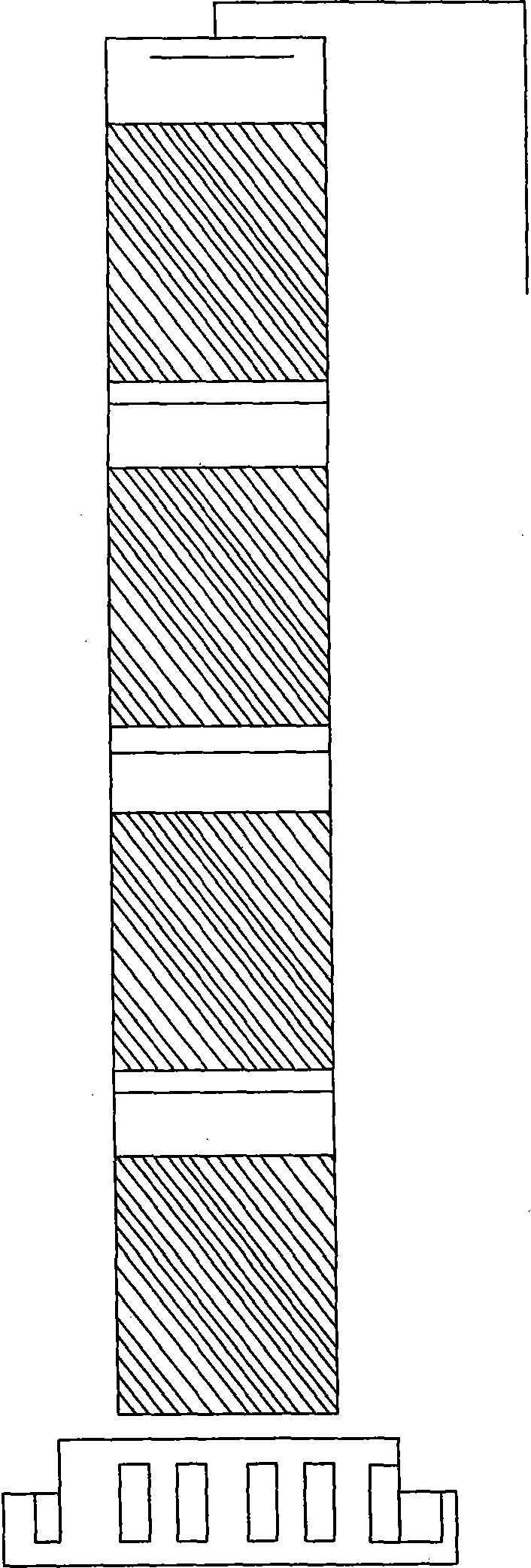
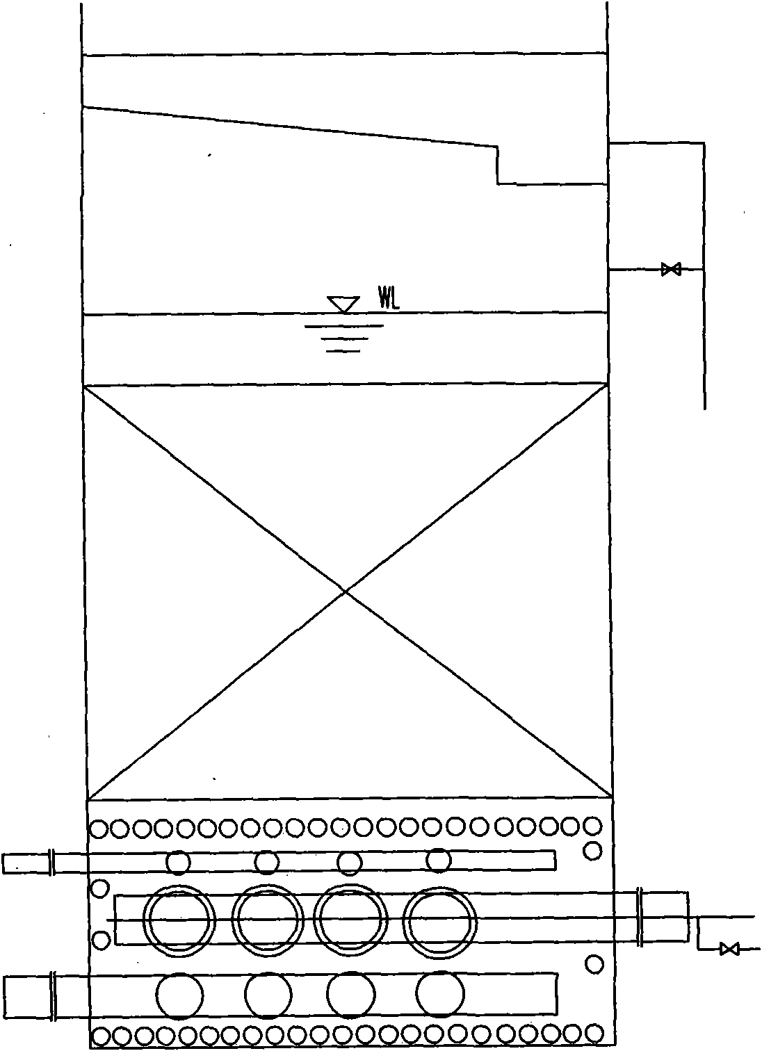
technical field [0001] The invention relates to a biological filter tower, which belongs to the technical field of water treatment equipment. Background technique [0002] At present, there are two main types of water treatment equipment that are generally known through biofilm filtration: one is tower biofilter such as figure 1 shown; the second is the biological aerated filter (or filter tower) such as figure 2 shown. The tower type biological filter usually has a height of 8-24m and a diameter of 1-3.5m. It is generally composed of a tower body, filter material, water distribution system, ventilation and drainage devices. The existing tower-type biological filter has a high construction cost due to the high tower body; and the filtering effect is limited due to the single filter material. Biological aerated filter usually consists of tank body, filter material, supporting layer, water distribution system, water outlet system and pipeline, ventilation and control syste...

Claims


Application Information

Patent Timeline
IPC IPC(8): C02F3/02C02F3/10
CPCY02W10/10
Inventor 唐志坚张跃峰丁志斌聂永平连小莹管正军汪毅王秀春曹传新张磊
Owner PLA UNIV OF SCI & TECH
Learn More