
Thickness control compensation method of strip steel head part when welding line passes through rack

A technology of thickness control and compensation method, which is applied in the field of roll calibration for empty roll gaps, and can solve problems such as strip breakage in rolling mills, inability to completely eliminate roll depression tilt, and piled steel

Active Publication Date: 2010-07-21
BAOSHAN IRON & STEEL CO LTD
View PDF4 Cites 35 Cited by
  • Summary
  • Abstract
  • Description
  • Claims
  • Application Information

AI Technical Summary

Problems solved by technology

[0006] The disadvantages of the prior art are: since the thickness of the tinplate is generally less than 0.3 mm, the requirements for thickness control are relatively high, and the existing roll calibration method cannot completely eliminate the actual rolling inclination of the roll, so the thickness distribution of the strip along the width direction is uneven. Uniform, there are regular wedge defects in the strip
In addition, due to the serious inclination of the roll system, the oil film bearings often burn out during high-speed operation, resulting in serious strip breakage and piled steel in the rolling mill, which seriously affects the normal production of the rolling mill

Method used


Image

  • Thickness control compensation method of strip steel head part when welding line passes through rack
  • Thickness control compensation method of strip steel head part when welding line passes through rack
  • Thickness control compensation method of strip steel head part when welding line passes through rack

Examples


Embodiment Construction

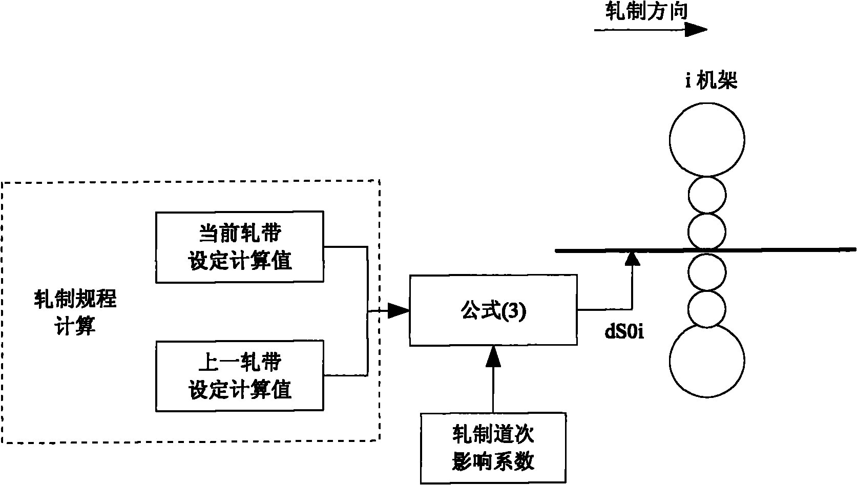
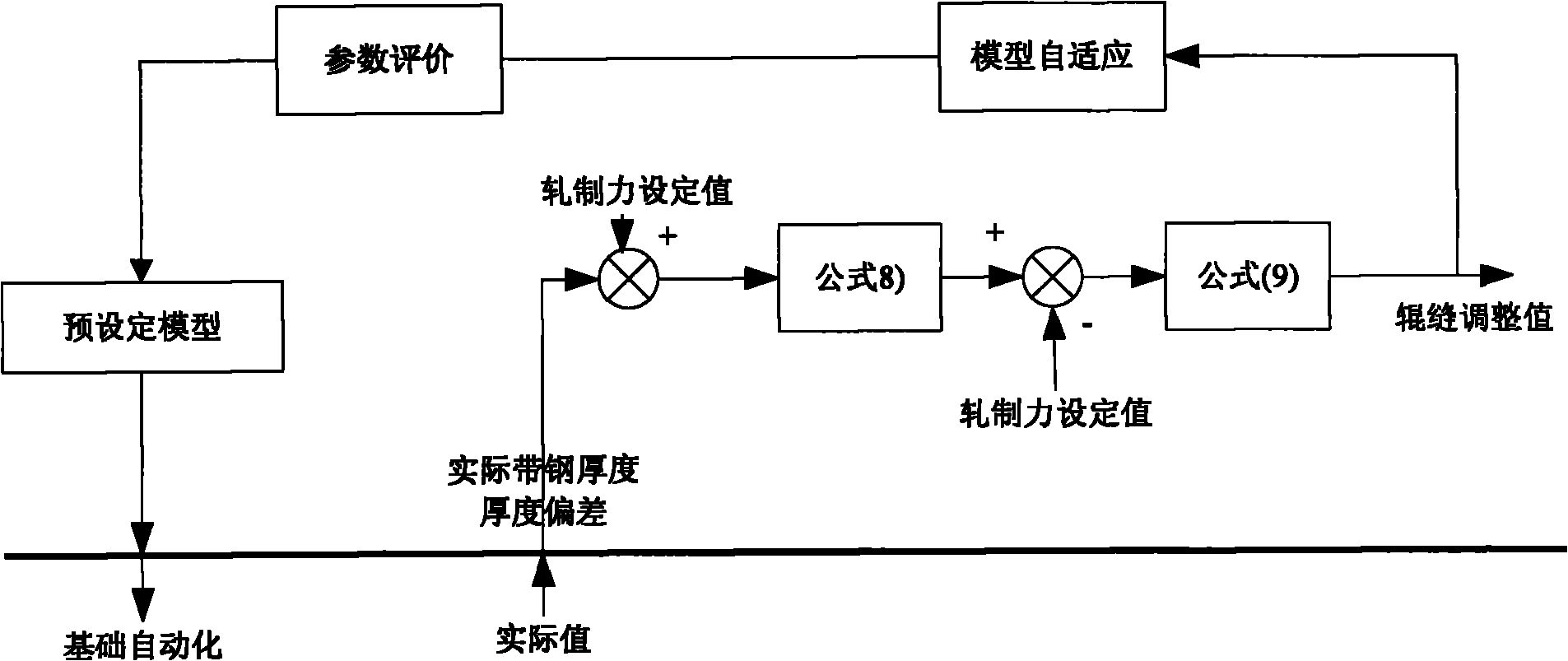
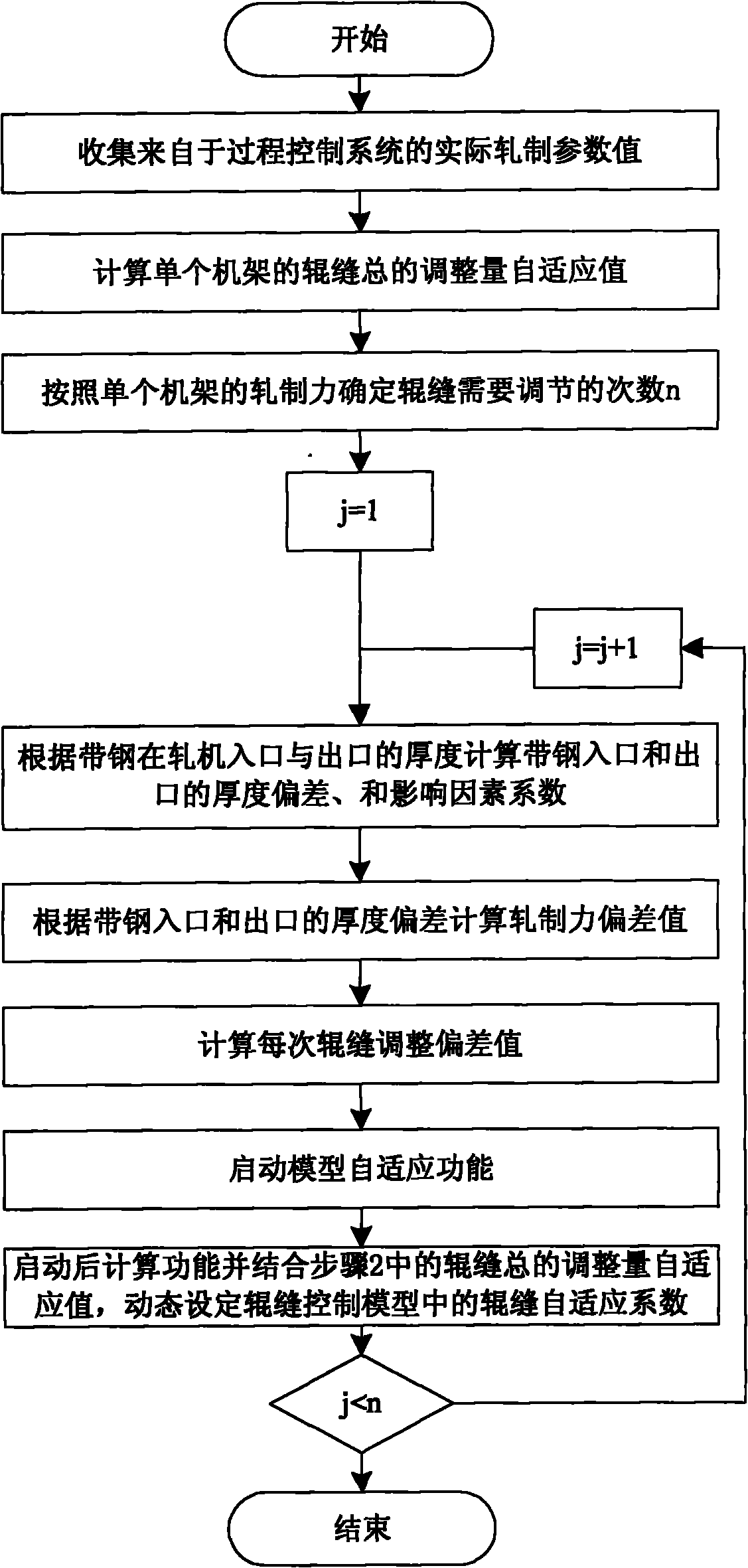
[0057] Attached below Figure 1-5 A preferred embodiment of the present invention will be introduced in detail.

[0058] like Figure 1-3 As shown, a method for controlling and compensating the thickness of the strip steel head when a weld seam passes through a frame of the present invention comprises the following steps:

[0059] Step 1. Collect the actual rolling parameter values ​​from the process control system according to each cycle, including: P rolling force, KN; h strip thickness, mm; total tension, unit KN / mm 2 ;Strip speed;Roll gap height. If conditions permit, the roll gaps on the operating side and the driving side can be collected separately. Using these actual parameters, the model can calculate the roll gap, and analyze and compare with the model pre-calculated results and actual measurement results, so as to further optimize the preset in the future. Determine the precision of the calculation.

[0060] Step 2. When the weld seam passes through the stand, t...


PUM

PropertyMeasurementUnit
thicknessaaaaaaaaaa

Abstract

The invention introduces a thickness control compensation method of a strip steel head part when a welding line passes through a rack, which comprises the following steps: 1, collecting actual rolling parameter values from a process control system; 2, calculating the total adjustment amount self-adaption value of roll-gaps of a single rack; 3, determining the required adjustment time n of the roll-gap according to the roll force of the single rack; 4, setting j to be equal to 1; 5, calculating thickness deviation delta hj-1, delta hj and influencing coefficient factor of the inlet and the outlet of the strip steel according to the thickness of the strip steel at the inlet and the outlet of a rolling mill; 6, calculating rolling force deviation value according to the thickness deviation of the inlet and outlet of the strip steel; 7, calculating roll-gap adjustment deviation value of each time; 8, starting the self-adaptation function of a model; 9, starting calculating function, and dynamically setting roll-gap self-adaptation coefficients in a roll-gap control model by combing the total adjustment quantity self-adaptation value of the roll-gap in the step 2; and 10, carrying out the step 5 when j is less than n and j=j+1; and finishing the process when j is more than or equal to n. The method ensures that the indication error length of thickness of the strip steel head part is controlled.

Description

technical field [0001] The invention relates to a roll calibration control process in steel rolling, in particular to a roll calibration method for empty roll gaps suitable for tinplate cold rolling mills. Background technique [0002] In the existing cold tandem production process, how to control the thickness accuracy of the strip at both ends of the weld is an important research topic when the specification is dynamically changed. Since the thickness accuracy is a very critical quality index of cold-rolled strip steel, reducing the over-tolerance length of the strip steel at both ends of the weld is an important goal of cold-rolled strip steel. Technicians have also adopted many new methods to improve the thickness control. Strip thickness control accuracy. For example, roll gap position control (patent No. US4125004A, patent No. US4244025A), through online measurement of strip inlet thickness and exit thickness deviation, pre-control and feedback control of roll gap pos...

Claims


Application Information

Patent Timeline
Patent Type & Authority Applications(China)
IPC IPC(8): B21B37/58
Inventor 羌菊兴赵会平王欣舒萦凌鹰鹤
Owner BAOSHAN IRON & STEEL CO LTD
Learn More