
Loudspeaker vibration sound film

A technology of loudspeaker and sound film, applied in the direction of sensor, diaphragm structure, electrical components, etc., can solve the problems of insufficient high frequency extension, insufficient vocal clarity, bulky loudspeaker, etc., and achieve the effect of increasing internal loss

Inactive Publication Date: 2010-07-14
金旭芳 +1
View PDF5 Cites 5 Cited by
  • Summary
  • Abstract
  • Description
  • Claims
  • Application Information

AI Technical Summary

Problems solved by technology

The loudspeaker industry has also made great progress, but there are still some shortcomings as follows. The existing speaker cones and sound diaphragms are all cone-shaped, and the processed speakers are relatively bulky and take up space. There is also the existing NXT plane. Although the sound film of the honeycomb panel reduces the volume, in terms of sound quality (low frequency is not rich enough, human voice is not clear enough) and curve (high frequency extension is not enough)
For the current development of the electro-acoustic industry, the development of new materials and technology has promoted the development of the electro-acoustic industry, but now many speakers have not changed much, and the speakers with good low frequency are quite bulky and too large. Car speakers are such speaker products. The loudspeakers with large volume and high frequency are very lacking, so there are coaxial speakers. The coaxial speakers also have the problem of being too large. With the development of technology and the use of space, many The release of new products, such as LED TVs, LCD TVs, and notebook computers, hope that the speakers have rich low frequencies, clear and bright intermediate frequencies, and high-frequency extension are the pursuit of modern consumers.

Method used


Image

  • Loudspeaker vibration sound film
  • Loudspeaker vibration sound film

Examples


Embodiment Construction

[0023] The present invention is implemented like this:

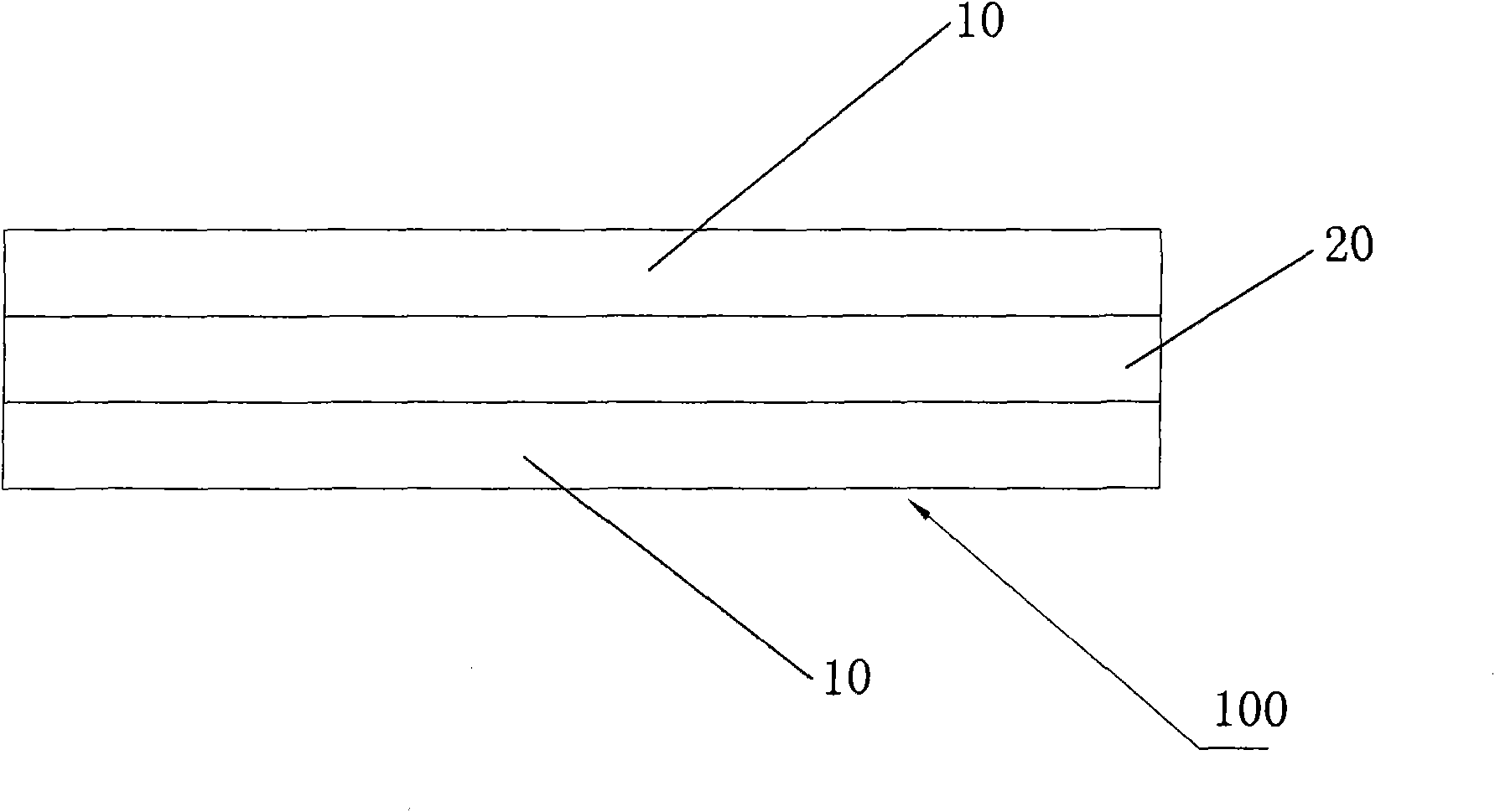
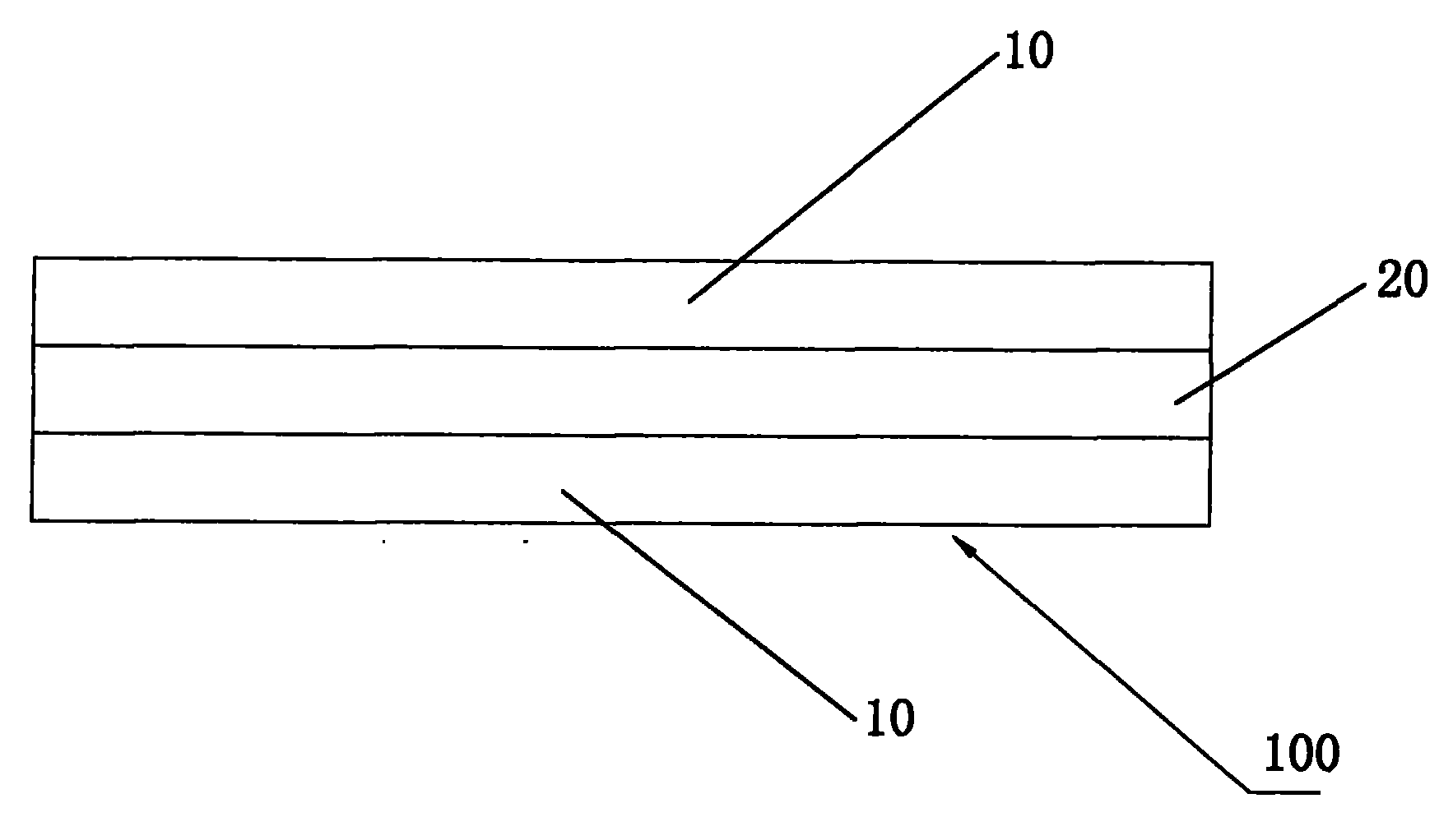
[0024] A loudspeaker vibrating sound membrane is used for a loudspeaker. The sound membrane 100 is composed of a fiber layer 10 , a balsa wood layer 20 and a fiber layer 10 laminated in sequence.

[0025] The fiber layer 10 is carbon fiber cloth, glass fiber cloth, basalt fiber cloth, aramid fiber cloth, paper fiber or chemical fiber.

[0026] The balsa wood layer 20 is made of balsa wood or wood pulp paper.

[0027] The outer surface of the fiber layer 10 is a pure plane or a concave-convex surface.

[0028] The fiber layer 10, the balsa wood layer 20 and the fiber layer 10 are laminated and then thermocompressed.

[0029] A kind of manufacturing process of above-mentioned loudspeaker vibrating sound film, this manufacturing process comprises the following steps:

[0030] 1), firstly, apply hot resin on both surfaces of the balsa wood layer;

[0031] 2), then attach the two fiber layers to the top and bottom surface...


PUM


Abstract

The invention relates to the field of electro-acoustic industry, in particular to an ultra-thin and ultra-light loudspeaker vibration sound film which has small vibration area and can generate mega bass. The loudspeaker vibration sound film is used in a loudspeaker, and the sound film is formed by bonding a fiber layer, a cork wood layer and another fiber layer together in turn. The beneficial effect of the loudspeaker vibration sound film of the invention is as follows: a fiber surface sound cone of the invention can meet the demand that a small-bore sound cone can generate mega bass and large-bore sound cone can generate high frequency sound. The fiber surface sound cone of the invention is prepared from a composite material and solves the problem that the cone and concave sound cone occupy too much space of the loudspeaker. When cork wood is adopted to prepare the composite material sound cone, the internal loss is increased by 50%, and when fiber cloth is used as the surface of the composite material, the Young modulus value of the sound cone is increased by 60% compared with NXT flat panel vibration film.

Description

technical field [0001] The invention relates to the field of the electroacoustic industry, in particular to a vibrating sound film of a loudspeaker that is ultra-thin and ultra-light, has a small vibration area and can produce super-bass. Background technique [0002] With the continuous progress of society, the living standards of our people are also constantly improving. The loudspeaker industry has also made great progress, but there are still some shortcomings as follows. The existing speaker cones and sound diaphragms are all cone-shaped, and the processed speakers are relatively bulky and take up space. There is also the existing NXT plane. Although the sound film of the honeycomb panel reduces the volume, it is not enough in terms of sound quality (low frequency is not rich enough, human voice is not clear enough) and curve (high frequency extension is not enough). For the current development of the electro-acoustic industry, the development of new materials and tech...

Claims


Application Information

Patent Timeline
IPC IPC(8): H04R7/02H04R31/00
Inventor 金旭芳周远泽
Owner 金旭芳
Learn More