
Three degree of freedom spherical motor with multiple physical field mixing driving

A hybrid drive and multi-physics technology, applied in the direction of generator/motor, piezoelectric effect/electrostrictive or magnetostrictive motor, electrical components, etc., can solve the problem of affecting the output power of the motor, strong noise, and limiting the output of the motor Torque and other issues, to reduce the number of stator windings, simplify the control system design, improve the effect of output torque

Inactive Publication Date: 2010-07-14
TIANJIN UNIV
View PDF6 Cites 23 Cited by
  • Summary
  • Abstract
  • Description
  • Claims
  • Application Information

AI Technical Summary

Problems solved by technology

However, the current ultrasonic spherical motor still has the following problems: 1. The pre-pressure device is not perfect
Compared with the size of the stator and rotor itself, the energy transfer interface of the ultrasonic motor is small, which limits the output torque of the motor
If the size of the stator is simply increased, although the contact area of ​​the stator and rotor can be increased, as the size increases, the resonant frequency of the stator decreases. When the resonant frequency is lower than the ultrasonic frequency band, the motor will generate strong noise. In addition, the ultrasonic motor The power is approximately proportional to the square of the resonant frequency, increasing the size of the stator will inevitably affect the output power of the motor

Method used


Image

  • Three degree of freedom spherical motor with multiple physical field mixing driving
  • Three degree of freedom spherical motor with multiple physical field mixing driving
  • Three degree of freedom spherical motor with multiple physical field mixing driving

Examples


Embodiment Construction

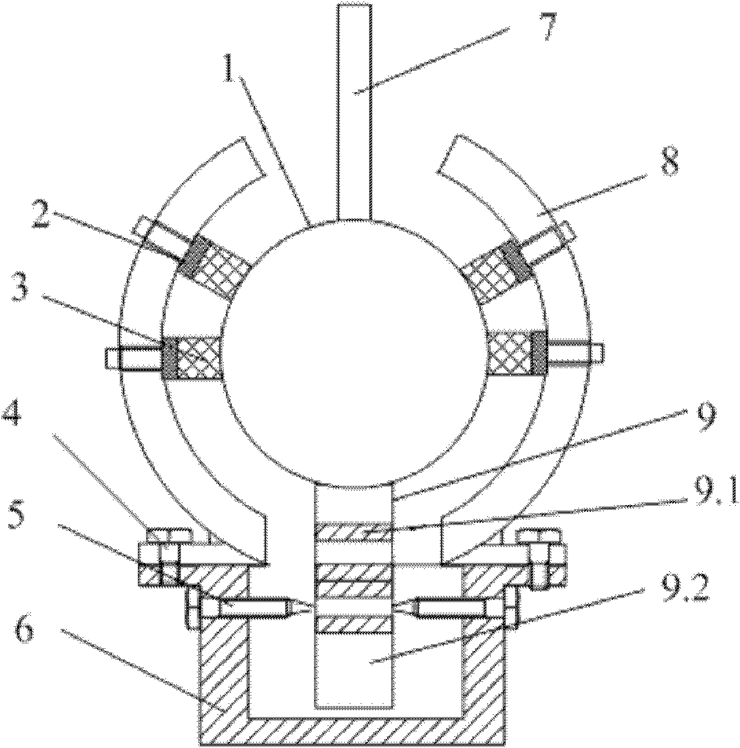
[0024] The multi-physics field hybrid drive three-degree-of-freedom spherical motor of the present invention includes three parts: a support part, a stator and a spherical rotor, wherein the support part includes a stator shell 8, a spring 2, a base 6 and a support bolt 5, and the stator includes a stator winding 3, an ultrasonic The vibrator 9 and the output shaft 7 are fixed on the spherical rotor 1. The basic structure of the motor is as figure 1 shown.

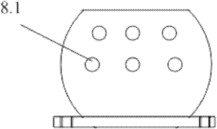
[0025] The stator case 8 is a spherical structure, fixed on the base 6 by bolts 4, a round hole is opened at the top of the stator case, and the output shaft 7 protrudes from it to connect the output torque and force. The size of the round hole is determined by the pitch angle of the motor. The upper hemisphere of the stator shell is evenly distributed along the equator with multi-layer winding installation holes 8.1. The installation holes 8.1 are through holes. The number of layers and density of the installation holes ...


PUM


Abstract

The invention belongs to the technical field of motor manufacture, and relates to a three degree of freedom spherical motor with multiple physical field mixing driving. The spherical motor comprises a supporting part, a stator and a spherical rotor, wherein the supporting part comprises a base and a spherical stator casing fixed on the base. The top end of the stator casing is provided with a circular hole. One layer or more than one layer of winding installation holes is uniformly distributed on the upper sphere of the stator casing in the direction parallel to the equator. The stator comprises a stator winding and an ultrasonic vibrator, wherein the stator winding consists of a winging shaft and a coil. The diameter of the winding shaft is slightly smaller than the inner diameter of the winding installation hole, and the top of the winding shaft penetrates through a compression spring and is arranged in the winding installation hole. The ultrasonic vibrator is fixed on the base, and the upper end of the ultrasonic vibrator is in an inner cone shape, and is matched with the spherical rotor. The spherical rotor is uniformly embedded in a multilayer permanent magnet pole along the direction parallel to the equator. The invention has reliable structure, improves the torque characteristic of the motor, and enhances the design flexibility of the motor control system.

Description

technical field [0001] The invention belongs to the technical field of motor manufacturing and relates to a three-degree-of-freedom spherical motor. Background technique [0002] With the advancement of science and technology, the application range of multi-degree-of-freedom motion mechanisms is becoming wider and wider. Traditional multi-degree-of-freedom motion is realized by combining multiple single-degree-of-freedom motors, which inevitably brings about problems such as large mechanism, low transmission precision, and difficult control. Therefore, the research of multi-degree-of-freedom motors and control systems has attracted more and more attention. Among them, spherical motors that can realize three-degree-of-freedom motions of pitch, tilt and rotation have wider application prospects, but the problems involved are also more complicated. [0003] Ultrasonic spherical motor is a new type of multi-degree-of-freedom motor that utilizes the inverse piezoelectric effect ...

Claims


Application Information

Patent Timeline
IPC IPC(8): H02N2/00
Inventor 夏长亮李斌史婷娜李洪凤李桂丹
Owner TIANJIN UNIV
Learn More