Eureka AIR delivers breakthrough ideas for toughest innovation challenges, trusted by R&D personnel around the world.

Laser three-dimensional imaging device based on single-photon detector

A single-photon detector, laser three-dimensional imaging technology, applied in the direction of measuring devices, optics, instruments, etc., can solve the problems of large system volume and power consumption, difficult to realize hidden target imaging detection, weak target echo, etc., to achieve The effect of miniaturization

Inactive Publication Date: 2010-07-14
SHANGHAI INST OF TECHNICAL PHYSICS - CHINESE ACAD OF SCI
View PDF0 Cites 85 Cited by
  • Summary
  • Abstract
  • Description
  • Claims
  • Application Information

AI Technical Summary

Problems solved by technology

On the one hand, these methods cause excessive system volume and power consumption; on the other hand, they limit the increase of laser repetition rate, resulting in low frame rate of 3D imaging.
In addition, in ground remote sensing and some military fields, detection objects are often hidden behind vegetation or artificial camouflage, and the target echo is generally extremely weak after a large attenuation. Limited by the sensitivity of the detector, imaging detection of hidden targets is difficult to achieve
[0004] In short, the current laser three-dimensional imaging device is limited by the detection sensitivity, it is difficult to detect hidden targets, and when the action distance is long, the requirements for the energy of the laser and the aperture of the receiving telescope are high, and it is difficult to achieve system miniaturization and high frame rate picture

Method used

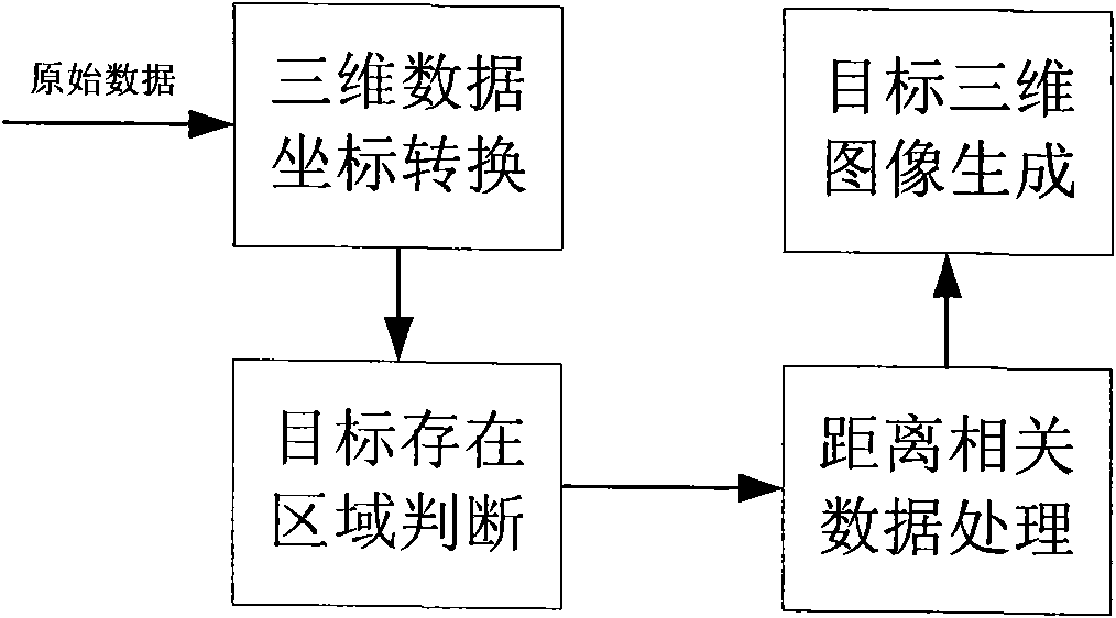

Image

  • Laser three-dimensional imaging device based on single-photon detector
  • Laser three-dimensional imaging device based on single-photon detector
  • Laser three-dimensional imaging device based on single-photon detector

Examples


Embodiment

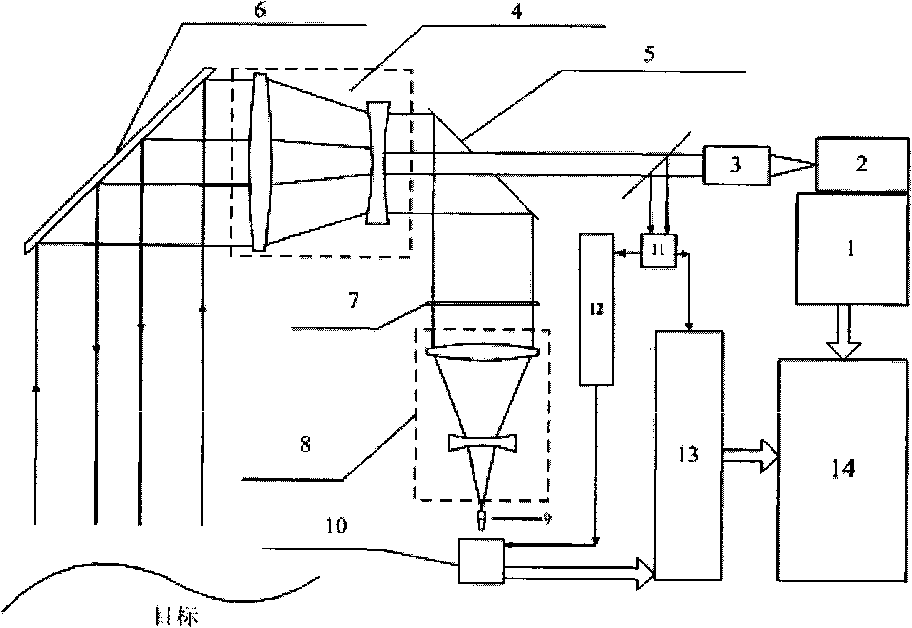
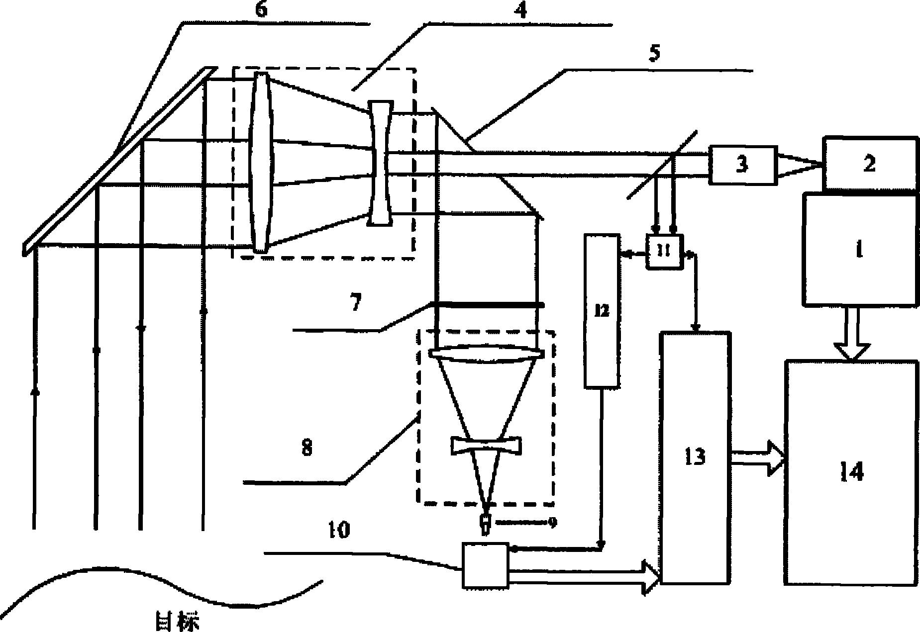
[0046] Such as figure 1 , the laser three-dimensional imaging device of the present invention comprises a position and attitude measuring unit 1, a pulsed laser 2, a collimating mirror 3, a transmitting-receiving shared telescope 4, a transmitting-receiving beam splitter 5, a scanning mirror 6, a spectral filter 7, a combination Lens group 8 , spatial filter 9 , double-gated single-photon detection unit 10 , laser emission detection unit 11 , gating signal generation unit 12 , multi-arrival pulse time interval measurement unit 13 and data processing unit 14 .

[0047]The light pulse emitted by the pulsed laser 2 passes through the collimating mirror 3 and is divided into two parts. One part triggers the laser emission detection unit to generate an initial signal, and the other part irradiates the target through the emission-reception spectroscope 5 and the emission-reception telescope 4 and receives the return signal. , is received by the double-gated single-photon detection u...


PUM

PropertyMeasurementUnit
Bandwidthaaaaaaaaaa
Core diameteraaaaaaaaaa

Abstract

The invention discloses a laser three-dimensional imaging device based on a single-photon detector, belonging to the technical field of photoelectric instruments. A target to be detected is irradiated by the laser pulse emitted by a pulsed laser via a scanning system; the returning photons are received by a receiving / emitting co-axial optical system, i.e., the returning photons are received by a double-gating single-photon detecting module via a spectral filter and a spatial filter and an arriving pulse is outputted, so that the photon flight time of the target measuring point can be measured by combining the laser emission detection and the multi-photon arriving pulse time; and a data processing unit is used for carrying out the coordinate conversion based on the position and attitude data, scanning mirror targeting data, and photon flight time of the three-dimensional imaging device, de-noising and three-dimensional image construction and correction, so as to output the reliable target three-dimensional range image. The invention solves the problems that the existing laser three-dimensional imaging device is incapable of penetrating vegetation and camouflage and being miniaturized when conducting long-distance operations.

Description

technical field [0001] The invention belongs to the technical field of photoelectric instruments, and specifically refers to a laser three-dimensional imaging device based on a single-photon detector, which is used to detect targets under vegetation or camouflage, and can quickly obtain high-resolution laser three-dimensional images of distant targets. Background technique [0002] Compared with the traditional two-dimensional grayscale image, the three-dimensional range image can provide richer target information such as distance, orientation, size and attitude, etc., which can greatly improve the efficiency of target recognition and classification. Laser 3D imaging based on time-of-flight is a common and important method for 3D imaging of targets. It uses a pulsed laser beam to irradiate the target, receives the reflected echo through the photodetector, obtains the distance information of the target surface by calculating the flight time of the laser pulse, and combines tw...

Claims


Application Information

Patent Timeline
IPC IPC(8): G01S17/89G02B27/22
Inventor 郭颖舒嵘况耀武黄庚华
Owner SHANGHAI INST OF TECHNICAL PHYSICS - CHINESE ACAD OF SCI
Why Eureka
Eureka Blog
Learn More